Membrane separation type activated sludge process – indoor experiment
村上定瞭(水浄化フォーラム), Sadaaki Murakami (Water & Solutions Forum)
活性汚泥法の総目次
Ⅰ. 活性汚泥法とは
Ⅱ. 基本設計・操作因子
Ⅲ. 回分型-室内実験
Ⅳ.連続型-室内実験
Ⅴ.活性汚泥の悪化と対策-室内実験
Ⅵ.高酸素濃度型-余剰汚泥なし
Ⅶ.汚泥減量型
Ⅷ.膜分離型-室内実験(本ページ)
Total table of activated sludge process
Ⅰ. What is the activated sludge process?
Ⅱ. Basic design and operation factors
Ⅲ. Batch type – indoor experiment
Ⅳ. Continuous type – indoor experiment
Ⅴ. Deterioration of activated sludge and countermeasures
Ⅵ. High oxygen concentration type – no excess sludge
Ⅶ. Sludge reduction type
Ⅷ. Membrane separation type – indoor experiment (this page)
1.はじめに
生物処理、特に、活性汚泥法において、膜によるSS分離は物理的に安定して行われることから、標準的な沈殿槽でのSS分離の良否に配慮するこがなく、清浄な処理水が得られ、生物処理工程の運転管理が容易となる。このことから、微生物の濃度を極めて高く保持できるので、高濃度排水をコンパクトな設備での処理が可能となる。このことからし尿や浄化槽汚泥の処理、高濃度食品排水や特殊な工場排水の処理に適用されている。一般的に生物濃度は10,000~20,000mg/Lで運転されるが、小生の経験では50,000~60,000mg/Lで運転したこともある。
一方で、SS分離に膜を利用するには、次のような課題が挙げられる。
1. Introduction
In biological treatment, especially in the activated sludge method, SS separation by membrane is physically stable, so clean treated water can be obtained without considering the quality of SS separation in a standard settling tank. Therefore, operation management of the biological treatment process becomes easy. As a result, the concentration of microorganisms can be kept extremely high, and high-concentration wastewater can be treated with compact equipment. For this reason, it is applied to the treatment of night soil and septic tank sludge, the treatment of highly concentrated food wastewater and special factory wastewater. In general, the biological concentration is 10,000 to 20,000 mg/L. In editor’s experience, it was able to operate even at 50,000 to 60,000 mg/L, when the oxygen supply was sufficient.
On the other hand, using a membrane for SS separation has the following problems.
(1)膜システムの課題
1) 膜モジュールの高価格、2) ろ過能力の低下と分離膜の再生、3) 膜の劣化と更新、4) 膜システムを稼働する電気代などが挙げられる。
(1) Issues of membrane system
1) High price of membrane module, 2) Decrease of filtration capacity and regeneration of separation membrane, 3) Deterioration and renewal of membrane, 4) Electricity cost to operate membrane system.
(2)酸素補給の課題
5) 高濃度微生物の維持のための空気(酸素)の補給方法の工夫、6) 高濃度混合液の粘度が高く、通気に伴う激しい発泡を伴うなどの課題がある。
過去において、生物反応槽と膜分離モジュールは分離されていたが、今日では、反応槽内に分離膜を設置する方式が多く採用されている。ここでは、実験室での小型コンパクトな装置を用いて膜分離活性汚泥法の特徴を理解・経験することを目的としているので、曝気槽と膜モジュールを分離した事例を紹介する。また、膜モジュールとしては経済性と空間効率の視点から平幕型が多く採用されているが、維持管理の容易なチューブラー型を活用する。なお、分離膜の種類・特性については、他のページに記載してあるので、参照されたい。
(2) Challenges of oxygen supplementation
5) There are problems such as devising a method of supplying air (oxygen) to maintain high-concentration microorganisms, 6) the viscosity of a high-concentration mixed liquid is high, and violent foaming accompanying aeration.
In the past, the biological reaction tank and the membrane separation module were separated, but today, the method of installing a separation membrane in the reaction tank is often adopted. Here, we aim for students or biginners to understand and experience the characteristics of the membrane separation activated sludge method using a small and compact device in the laboratory, so we will introduce an example of separating the aeration tank and the membrane module. As the membrane module, the flat curtain type is often used from the viewpoint of economy and space efficiency, but the tubular type is used because it is easy to maintain. For the types and characteristics of separation membranes, refer to another page.
2.実験装置
(1)実験装置の構成
実験装置の主な構成は、1) 曝気槽、2) 空気供給装置、3) 膜分離モジュールおよび消泡装置である。
曝気槽には、原水供給、計測制御器、空気供給配管、分離膜モジュール配管が設置されている。計測制御項目はDO、pHおよび水位である。曝気槽の有効容積は10Lで、膜モジュールおよび配管系を含めた総容積は12Lである。
空気供給装置(図1-①)は、循環ポンプ、エジェクターから構成され、微細空気導入液が曝気槽へ循環している。
膜分離モジュール(図1-②)は、曝気槽からの混合液をUF膜へ循環し、ろ過液が排出される。循環ポンプ経路には圧力調整弁、圧力計が設置されている。循環ポンプは、曝気槽の水位計により制御されている。
消泡装置(図1-③)は、曝気槽上部壁面に設置したチューブから曝気槽からの循環液を散布・消泡している。
2. Experimental device
(1) Components of experimental equipment
The main components of the experimental equipment are 1) aeration tank, 2) air supply device, 3) membrane separation module and defoaming device.
Raw water supply, measurement controller, air supply pipe, and separation membrane module pipe are installed in the aeration tank. The measurement control items are DO, pH and water level. The effective volume of the aeration tank is 10L, and the total volume including the membrane module and the piping system is 12L.
The air supply device (Fig.1-①) consists of a circulation pump and an ejector, and the fine air introduction liquid circulates to the aeration tank.
The membrane separation module (Fig.1-②) circulates the mixed liquor from the aeration tank to the UF membrane and discharges the filtrate. A pressure regulating valve and a pressure gauge are installed in the circulation pump path. The circulation pump is controlled by the water level gauge in the aeration tank.
The defoaming device (Fig.1-③) sprays and defoams the circulating fluid from the aeration tank from the tube installed on the upper wall of the aeration tank.
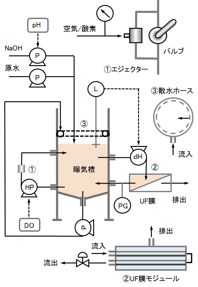
図1 膜分離活性汚泥の室内実験装置の概要
Fig.1. Outline of laboratory equipment for membrane separation activated sludge.
(2)構成要素の詳細
(a) 空気供給とアスピレーター(エジェクター)
高濃度の微生物に酸素を供給するため、通常の散気きよる方法では不十分である。混合液の循環系にアスピレーター(エジェクター、下記の写真 3-3 を参照)を設置して微細な空気を導入することで酸素供給を行う。図1-①に示すように、アスピレーターへの循環液量をバルブで制御して空気の供給量の調整を行う。アスピレーターの空気流入量は流量計に接続して計測する。
流量制御用バルブは写真1-③に示すステンレス製とする。青銅製はピンホールが形成される恐れがあるので、避ける。アスピレーターはステンレス製(写真1-①)またはテフロン製(写真1-②)でよいが、塩類濃度の高い腐食性排水にはテフロン製が適切である。アスピレーターと空気流量計の接続は真空ポンプ用耐圧ホース(写真1-④)を用いる。
なお、微生物濃度が50,000mg/L前後の極めて高濃度の場合には、空気では酸素供給が不十分であるので、純酸素を供給する。
(2) Details of components
(a) Air supply and aspirator (ejector)
Since oxygen is supplied to high-concentration microorganisms, the usual aeration-based method is insufficient. Oxygen is supplied by installing an aspirator (ejector, see Photo 3-3 below) in the circulation system of the mixed liquor and introducing fine air. As shown in Fig.1-①, the amount of circulating fluid to the aspirator is controlled by a valve to adjust the air supply amount. The air inflow of the aspirator is connected to a flow meter and measured.
The flow control valve shall be made of stainless steel as shown in Photo 1-③. Avoid bronze, as it may form pinholes. The aspirator may be made of stainless steel (Photo 1-①) or Teflon (Photo 1-②), but Teflon is suitable for corrosive wastewater with high salt concentration. Use a pressure hose for the vacuum pump (Photo 1-④) to connect the aspirator to the air flow meter.
If the microorganism concentration is extremely high, around 50,000 mg/L, the oxygen supply is insufficient with air, so pure oxygen is supplied.
(b) 消泡シャワー
活性汚泥濃度の増加とともに、供給空気量および混合液粘度はそれぞれ増加し、発砲が激しくなる。これを防ぐため、混合液を循環し、曝気槽上部から散水する。散水は、円形型にしたチューブを曝気槽上部内壁に設置(図1-③、写真 3-2 を参照)、このチューブの下面の小穴から曝気槽内壁へ向けて散水することで、消泡が可能となる。
(b) Defoaming shower
As the concentration of activated sludge increases, the amount of air supplied and the viscosity of the mixed liquor increases, resulting in severe firing. In order to prevent this, the mixed linquor is circulated and water is sprinkled from the upper part of the aeration tank. For water sprinkling, a circular tube is installed on the inner wall of the aeration tank upper part (Fig.1-③, see Photo 3-2 below), and the linquor can be defoamed by spraying water from the small holes on the lower surface of this tube toward the inner wall of the aeration tank.
(c) 分離膜とモジュール
コンパクトなベンチスケール実験では、維持管理上、観察できるように透明容器に取り付けたチューブラー型の分離膜が望ましい。本実験では、分画分子量20,000、内径1.15cm、長さ57.2cm、膜面積170cm2のチューブラー型、4本を直列に接続し(下記の写真2-Cを参照)、差圧1.0気圧、平行流速1.7m/sで稼働した。活性汚泥濃度30,000~60,000mg/Lの連続運転(水位計によるon-off制御)を行ったところ、初期ろ過能力は16L/dで、約6ヶ月後でも15L/dであり、この程度の期間でのろ過能力の低下は認められなかった。
(c) Separation membrane and module
In a compact bench-scale experiment, a tubular separation membrane attached to a transparent container for observation is desirable for maintenance. In this experiment, four tubular types with a molecular weight cutoff of 20,000, an inner diameter of 1.15 cm, a length of 57.2cm, and a membrane area of 170cm2 were connected in series (see Photo 2-C below) and operated at a differential pressure of 1.0atm and a parallel flow velocity of 1.7m/s. After continuous operation (on-off control by water level meter) with activated sludge concentration of 30,000 to 60,000 mg/L, the initial filtration capacity was 16L/d, and it was 15L/d even after about 6 months. No decrease in filtration capacity was observed.
(d) 水位計とフリップフロップ回路
原液は連続投入し、フロート型水位計を設置してUF膜モジュールの循環ポンプをon-off制御し、反応槽内の水位を保ち、混合液をろ過した。発泡しているので、水位計はフロート型を使用する。また、曝気槽には、空気供給系、UF膜モジュール循環系、消泡系循環系があり、反応槽の水面は振動しているので、水位計と連動したUF膜モジュール循環ポンプの制御には、チャタリングを防ぐ目的で、フリップ-フロップ回路(下記の写真3-4を参照 )により、セット(H-レベル)・リセット(L-レベル)によるon-off制御を行う。
(d) Water gauge and flip-flop circuit
The raw wastewater was continuously charged, the float type water level meter was installed, the circulation pump of the UF membrane module was controlled on-off, the liquor level in the reaction tank was maintained, and the mixed liquor was filtered. Since it is foaming, a float type water level gauge is used. In addition, the aeration tank has an air supply system, a UF membrane module circulation system, and a defoaming system circulation system, and the liquor surface of the reaction tank is vibrating, so it is not possible to control the UF membrane module circulation pump linked with the liquor level gauge. In order to prevent chattering, a flip-flop circuit (see Photo 3-4 below) performs on-off control by setting (H-level) and reset (L-level).
(e) 循環系とポンプ
循環系のマグネットドライブ・ポンプ(HP、揚程10m)を連続稼働すると発熱するので、銅管を貼り付けた銅板をポンプ・モーターに取り付け、銅管に水道水を流し、冷却する。
差圧1atm程度であるが圧力の掛る循環系配管については、特にエジェクター系(図1-①)および膜モジュール系(図1-②)には、図2に示す強化ホース・ホースクリップやPVCの管・バルブ・接続部品などを用いて、漏れなどが生じないよう留意する。
(e) Circulation system and pump
If a magnetic drive pump (HP, pump head 10m) of circulation system is operated continuously, it will generate heat. Therefore, attach a copper plate with a copper pipe attached to the pump motor, and run tap water on the copper pipe to cool it.
Regarding the circulation piping with a pressure difference of about 1atm, but with pressure, especially for the ejector system (Fig.1-①) and the membrane module system (Fig.1-② ), the reinforced hose/hose clip and PVC shown in Fig.2 should be used. Use pipes, valves, connecting parts, etc. to prevent leakage.
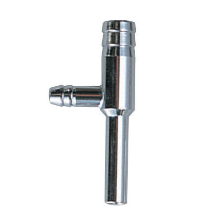
① アスピレイター(ステンレス),
Aspirator (stainless steel.)
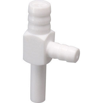
② アスピレイター(テフロン), Aspirator (Teflon).
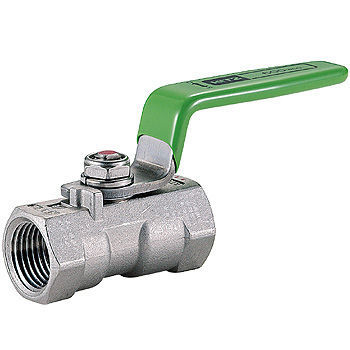
③ アスピレイター流量制御,
Aspirator flow control.
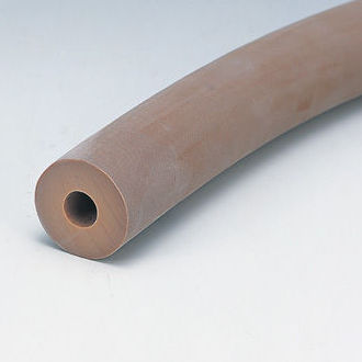
④ 耐圧ホース(天然ゴム),
Pressure hose (natural rubber).
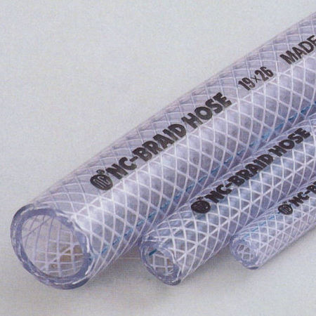
⑤ 強化ホース,
Reinforced hose.
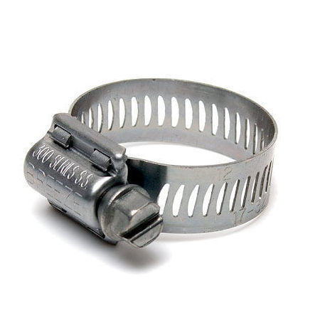
⑥ ホースクリップ,
Hose clip.
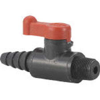
⑦ 接続バルブ(PVC), Connection valve (PVC).
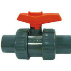
⑧ 接続バルブ(PVC),
Connection valve (PVC).
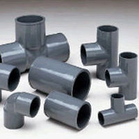
⑨ 接続部品(PVC),
Connection part (PVC).
Photo 1. Example of parts of indoor experimental equipment for membrane-separated activated sludge.
3.運転と管理
(1)負荷と汚泥濃度
沈殿分離を用いる活性汚泥法では、曝気槽と沈殿槽の設計・運転管理には負荷と汚泥濃度が相互に深く関係している。膜分離活性汚泥では、曝気槽と膜分離は別々に設計と運転管理が可能である。
負荷を大きくして汚泥濃度を高く設定すると酸素供給力が制約因子となる。汚泥濃度を高くすると(20,000mg/L以上)、混合液の粘度が高くなるとともに、空気供給量も増加し、発泡が激しくなる。酸素供給量と発泡阻止の限界が負荷・汚泥濃度の設定値となるので、それぞれの設備に適切な値を実験的に求める。実験室レベルでは汚泥濃度50,000mg/L程度まで可能であるが、一般的には8,000~15,000mg/Lで運用されている。
3. Operation and management
(1) Load and sludge concentration
In the activated sludge method that uses sedimentation, load and sludge concentration are closely related to each other in the design and operation management of the aeration tank and settling tank. In membrane activated sludge, aeration tank and membrane separation can be designed and operated independently.
When the load is increased and the sludge concentration is set high, the oxygen supply capacity becomes a limiting factor. When the sludge concentration is increased (20,000 mg/L or more), the viscosity of the mixed liquor is increased, the air supply amount is increased, and the foaming becomes severe. Since the oxygen supply rate and the limit of foaming inhibition are set values for load and sludge concentration, we will experimentally determine the appropriate values for each facility. At the laboratory level, sludge concentrations of up to 50,000 mg/L are possible, but in general, it is operated at 8,000 to 15,000 mg/L.
(2)SRTと余剰汚泥
SRTを長くすると余剰汚泥の発生量は少なくなる。SRTを長くすると、汚泥の老化が進み、汚泥の活性低下と混合液の粘性増加などが起こる。汚泥の活性度と性状を考慮して、実験的にSRTと汚泥引抜量を設定する。
(2) SRT and excess sludge
The longer the SRT, the less the amount of excess sludge generated. If the SRT is lengthened, the sludge will age and the sludge activity will decrease and the viscosity of the mixture will increase. The SRT and sludge extraction volume are experimentally set in consideration of the activity and properties of the sludge.
(3)酸素供給
酸素供給法は、1) 散気装置、2) 散気圧力、3) 散気種類に分類される。散気装置には、微細気体の供給方法により、一般的な散気法、エジェクター法、機械的微細気体法などがある。気体の溶解量はその分圧に比例するので、密封加圧槽や深層槽への曝気がある。散気種類には、空気、酸素分圧の高い空気や純酸素の曝気がある。
高汚泥濃度・高負荷運転では、空気(酸素)の補給方法が重要な因子となる。空気の散気による運転では、原水組成にもよるが、汚泥濃度は10,000~20,000mgVSS/L程度が適切であろう。消泡剤添加や機械的消泡より、汚泥濃度をさらに増加することが可能となる。
エジェクター方式によれば、空気供給で汚泥濃度が20,000~30,000mg/Lまで可能で、さらに純酸素供給では50,000~60,000mg/L程度の運転が可能であるが、後者は経済性から考えて特殊なケースを除き実用化レベルでは難しい。
実験室での酸素供給法では様々な選択が可能であるが、実用的には、経済性と設置環境に沿った酸素供給法を採用すべきである。
(3) Oxygen supply
Oxygen supply method is classified into 1) diffuser, 2) diffuser pressure, and 3) diffuser type. The air diffuser includes a general air diffuser method, an ejector method, a mechanical fine gas method, and the like, depending on the method of supplying the fine gas. Since the amount of dissolved gas is proportional to its partial pressure, there is aeration in a sealed pressurizing tank or a deep tank. Aeration types include aeration of air, air with a high oxygen partial pressure, and pure oxygen.
In high sludge concentration and high load operation, the method of supplying air (oxygen) is an important factor. For operation by air diffusion, a sludge concentration of 10,000 to 20,000 mg/L is appropriate, depending on the composition of raw water. It becomes possible to further increase the sludge concentration by adding an antifoaming agent or mechanical defoaming.
According to the ejector method, sludge concentration of 20,000 to 30,000 mg/L is possible with air supply, and operation of 50,000 to 60,000 mg/L is possible with pure oxygen supply. It is difficult at the practical level except for the cases below.
Although various choices can be made in the oxygen supply method in the laboratory, practically, the oxygen supply method should be adopted according to the economical efficiency and the installation environment.
(4)膜モジュール
(a) 膜・モジュール選択
膜・モジュールの選択は、初期設備および長期間運転における経済性を総合的に考慮して選定する。
本ページでは、曝気槽の外部に設置したUF膜分離ユニットを用いた。最近では、曝気槽内に浸漬するMF膜ユニットが開発され、小規模処理場に採用されている。この理由は、1) 良質な処理水、2) 維持管理が容易、 3) 設備の省スペースなど上げられる。分離膜の洗浄も、自動化あるいはカートリッジ交換など、維持管理の簡素化が可能となっている。
(b) 膜洗浄
膜性能は稼働時間の経過とともに、劣化する。定間隔での逆洗システムと年数回間隔での洗浄が必要となる。
チューブラー型分離膜は、クロスフローにより膜表面での蓄積物質が剥離されるので、原水組成にもよるが、メーカー定格の運転条件では膜洗浄は半年~数年に1回程度である。また、水位計によるon-off制御では、加圧と減圧が繰り返され、減圧時に逆洗が行われる。UF膜は非対称型膜構造であり、膜の詰まり(ファウリング)も起こりぬくい。洗浄法は、原水組成により異なる。
原水中に金属片や小砂などの異物が混入すると、膜表面の破損の原因となる。一般的には、貯留槽や調整槽があれば、ここで沈降分離されるので特に問題となることは少ない。
写真の現像廃液(写真2)およびラーメン店の廃油脂(写真3)の膜分離活性汚泥処理に利用したUF膜の洗浄は年に1~2回程度であった。膜洗浄は、次亜塩素酸溶液に1日に浸漬し、水道水を通水して洗浄した。洗浄後のろ過速度は、使用前の速度に回復した。
(4) Membrane module
(a) Membrane/module selection
Select membranes and modules in consideration of the economic efficiency of initial equipment and long-term operation.
In this page, the UF membrane separation unit installed outside the aeration tank was used. Recently, an MF membrane unit that is immersed in an aeration tank has been developed and is being used in a small-scale treatment plant. The reasons are 1) good quality treated water, 2) easy maintenance, and 3) space saving of equipment. Cleaning of the separation membrane can be automated or the cartridge can be replaced, simplifying maintenance.
(b) Membrane cleaning
Membrane performance deteriorates over time. A backwash system at regular intervals and cleaning at intervals of several times a year are required.
In the tubular separation membrane, the accumulated substances on the membrane surface are peeled off by cross flow, so it depends on the composition of the raw water, but under the manufacturer’s rated operating conditions, membrane cleaning is performed once every half a year to several years. Further, in the on-off control by the water level meter, pressurization and depressurization are repeated, and backwashing is performed at the time of depressurization. The UF membrane has an asymmetric membrane structure, and clogging (fouling) of the membrane rarely occur. The cleaning method depends on the composition of raw water.
If foreign matter such as metal fragments or small sand gets into the raw water, it may damage the membrane surface. Generally, if there is a storage tank or adjustment tank, sedimentation and separation will occur here, so there is little problem.
Cleaning of the UF membrane used for the membrane separation activated sludge treatment of the photo developer waste liquid (Photo 2) and the waste oil and fat from the ramen restaurant (Photo 3) was done once or twice a year. The membrane was washed by immersing it in a hypochlorous acid solution for 1 day and passing tap water through it to wash it. The filtration rate after washing was restored to the rate before use.
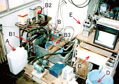
写真2 膜分離活性汚泥法の実験装置-懸濁重合・高分子製造工程排水への適用例
A:原水タンク、B:曝気槽、B 1:アスピレイター、B 2:空気流量計、B 3:混合液の水位計、C:膜分離モジュール、D:処理水、E:制御系の一部
Photo 2. Experimental equipment for membrane separation activated sludge method – Application example to wastewater from a suspension polymerization and polymer production process.
A: Raw water tank, B: Aeration tank, B1: Aspirator, B2: Air flow meter, B3: Mixed liquor level meter, C: Membrane separation module, D: Treated water, E: Part of control system.
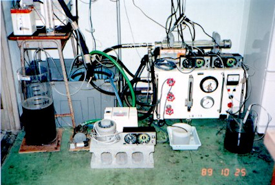
写真 3-1 実験装置の全景
Photo 3-1. Overall view of the experimental equipment.
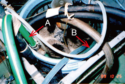
写真 3-2 曝気槽(図1-③を参照)
A:消泡シャワーの循環パイプ、B:円形状の散水パイプ
Photo 3-2 Aeration tank (see Fig.1-③).
A: Circulation pipe for defoaming shower, B: Circular sprinkling pipe.
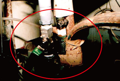
写真 3-3 エジェクター(図1-①を参照)
Photo 3-3 Ejector (See Fig.1-①).
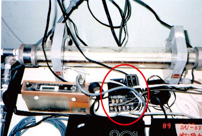
写真 3-4 フリップフロップ回路
Photo 3-4. Flip-flop circuit.
Photo 3. Experimental equipment for membrane separation activated sludge method – Application example to photo development waste liquid.
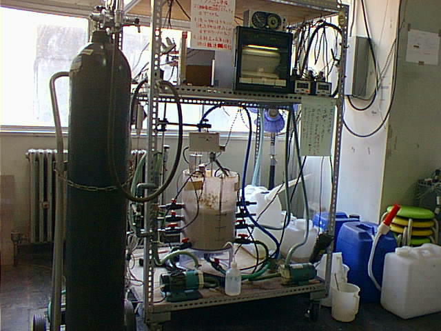
写真 4-1 実験装置の全景
Photo 4-1. Overall view of the experimental equipment.
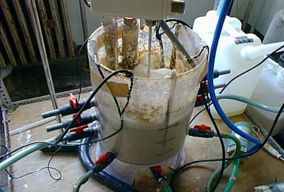
写真 4-2 曝気槽
Photo 4-2. Aeration tank.
Photo 4. Experimental equipment for membrane separation activated sludge method – Application example for animal fats and oils in oil traps at ramen stores (pure oxygen supply method).
4.まとめ
編者は、30数年前に、しまなみ海道にある島の「UF膜分離型し尿処理場」の建設に関与した。コンパクトで維持管理が容易であることから、当時、嫌気性消化と活性汚泥が主流であったし尿処理法に比べて、画期的なものであった。この開発に当たっての課題は、高負荷の活性汚泥槽への酸素供給と発泡への対策であった。循環する混合液のジェット流を曝気槽へ噴射して、空気中酸素を供給するとともに、消泡剤を添加した。インターネットで検索すると、現在でも稼働しているようである。現在は、浄化槽の普及により、し尿処理量は減少しているが、浄化槽汚泥の処理量が増加していることが推定される。
通常の活性汚泥法の維持管理には、知識および経験を要する。維持管理の人件費を考慮すると、初期投資は高価であるが、分離膜モジュール技術の進展もあることから、今後も、小規模の高濃度有機性廃水への処理技術として期待できる。
4. Summary
Thirty and several years ago, the editor was involved in the construction of the UF membrane-separated night soil treatment plant on an island on the Shimanami Kaido. Since it was compact and easy to maintain, anaerobic digestion and activated sludge were the mainstream at that time, and it was a breakthrough compared to the conventional night soil treatment system. The challenge in this development was the supply of oxygen to the highly loaded activated sludge tank and countermeasures against foaming. A jet stream of the circulating mixed linquor was jetted into the aeration tank to supply oxygen in the air and add an antifoaming agent. Searching on the Internet, it seems to be working now. Currently, the amount of night soil waste treated is decreasing due to the spread of septic tanks, but it is estimated that the amount of septic tank sludge is increasing.
Knowledge and experience are required to maintain and manage the normal activated sludge process. Considering personnel costs for maintenance, initial investment is expensive, but due to progress in separation membrane module technology, it can be expected as a treatment technology for small-scale high-concentration organic wastewater in the future.
掲載:2017年05月09日
更新:2020年08月14日(英語版を追加)
Published: May 9, 2017.
Updated: August 14, 2020 (English version added).
