Biofilm reactor and technology for water treatment
村上定瞭(水浄化フォーラム), Sadaaki Murakami (Water & Solutions Forum)
1.生物膜の機能と特徴
(1) 身の回りの生物膜の例
(2) 水域の生物膜モデル
(3) 生物膜法の工学的利用
2.生物膜法の反応槽
(1) 反応槽の方式と種類
(2) 散水ろ床法
(3) 接触曝気法
(4) 生物ろ過法
(5) 回転円盤法
(6) 流動床法
(7) 生物膜の洗浄・再生
3.担体の種類と選定
(1) 材質による分類
(2) 形状による分類
(3) 比重による分類
(4) サイズによる分類
(5) ろ床の支持体
(6) 担体の選定指標
4.生物膜利用の事例
(1) 水道水ー緩速ろ過
(2) 家庭排水-小型浄化槽
(3) 流動担体型活性汚泥法
(4) 工業排水ー難分解性有機物
(5) ゼロエミッション型水産養殖
(6) 河川浄化
5.生物ろ過の実験方法(別ページ)
(1) 観賞魚水槽
(2) 難分解性工業有機廃水
1. Function and characteristics of biofilm
(1) Examples of biofilms around us
(2) Biofilm model of water area
(3) Engineering use of biofilm method
2. Biofilm reactor
(1) Reaction tank method and type
(2) Sprinkling filter method
(3) Contact aeration method
(4) Biological filtration method
(5) Rotating disk method
(6) Fluidized bed method
(7) Biofilm cleaning and regeneration
3. Type and selection of carrier
(1) Classification by material
(2) Classification by shape
(3) Classification by specific gravity
(4) Classification by size
(5) Filter support
(6) Carrier selection index
4. Examples of biofilm utilization
(1) Tap water – Slow filtration
(2) Household drainage – Small septic tank
(3) Fluidized carrier type activated sludge process
(4) Industrial wastewater – Persistent organic matter
(5) Zero-emission aquaculture
(6) River purification
5. Experimental method of biological filtration (other pages)
(1) Ornamental fish aquarium
(2) Persistent industrial organic wastewater
自然界においては、河川・湖沼・海域では砂・礫・水草・海藻・珊瑚礁などの表面に生物膜が発達し、細菌類・小動物、魚の産卵・稚魚、大小の魚類などから構成される大きな生態系を形成している。
一方で、生物環境を人工的に制御して、目的とする浄化機能を有する生物膜を構築するシステムある。単独システムだけでなく、物理的・化学的・土木的手法も加えた多様な浄化システムがある。
生物膜法の応用例としては、1)魚礁・藻場の造成、2)水産養殖・活魚・観賞魚の水槽浄化、3)生活排水(戸別・集合住宅や事業所等)の浄化槽、4)大規模の上水・下水施設の清浄ろ過(緩速ろ過)、5)産業排水の浄化、6)河川・湖沼・海域の浄化など、用水・排水・環境水の各分野で幅広く活用されている。
ここでは、生活・産業排水の浄化だけでなく、河川・湖沼・海域の浄化を含めた広い意味での生物膜の機能とその応用例を解説する。
In the natural world, rivers, lakes and marine areas, a large ecosystem consisting of bacteria, small animals, fish spawning, fry, large and small fish, etc., where a biofilm develops on the surface of sand, gravel, aquatic plants, seaweed, coral reefs, etc.
On the other hand, there is a system that artificially controls the biological environment and constructs a biofilm having a desired purification function. In addition to a single system, there are various purification systems that include physical, chemical, and civil engineering techniques.
Examples of applications of the biofilm technology are to 1) fish reefs and seaweed beds, 2) water for fish culture, live fish in distribution route, and ornamental fish, 3) domestic wastewater at each house, housing, and offices where are ruaral areas, 4) large-scale water and sewage where are urban areas, 5) industrial water and wastewater, 6) rivers, lakes and marine areas.
Here, we will explain not only the purification of domestic and industrial wastewater, but also the functions of biofilms in a broad sense including purification of rivers, lakes and marine areas, and their application examples.
1.生物膜の機能と特徴
(1)身の回りや自然環境における生物膜の例
1) 台所・風呂などの「ぬるぬる」
台所の洗い桶・三角コーナー、風呂場の浴槽・床など、清掃しても1日もすると、「ぬるぬる」してくる。
2) 河川や海岸の砂・礫・岩などの皮膜
河川や海岸の砂・礫・岩などには、緑色から褐色など、色や厚さも様々な皮膜が、それらの表面を覆っている。
3) 水草・海藻
透明な河川や浅い海域の底には数十cm~数mの水草や海藻が繁茂している。これらの葉・茎には、泥のような物質が付着している。
2)・3)で述べた水域での付着物を顕微鏡で観察すると1μm前後の細菌類から数mmの微少動物類・植物類など様々な生物が混在して生活していることが分かる。水中の栄養分を摂取した細菌類・菌類・藻類、これらを捕食する原生・小動物など、食物連鎖の生態系を構成している。砂・礫・水草・海藻は、微小生物の生息場だけでなく、産卵・稚魚・小型魚の生息空間をつくっている。
また、1)で述べた「ぬるぬる」は細菌類が分泌した粘質物質で、細菌類が固体表面への付着能を有するのみでなく、微細固形物(高分子物質)の捕捉能を有する。この物質中には高分子を加水分解して低分子化(アミノ酸・有機酸・糖など)する酵素を含み、低分子化された物質を細胞膜を通して取り込んでいる。
1. Function and characteristics of biofilm
(1) Examples of biofilms around us and in the natural environment
1) “Slimy” in the kitchen, bath, etc.
Even if you clean the washing tub/triangular corner of the kitchen, the bathtub/floor of the bathroom, etc., these will become “slimy” within a day.
2) Films of sand, gravel, rocks, etc. on rivers and coasts
Sand, gravel, rocks, etc. on rivers and coasts are covered with coatings of various colors and thickness, such as green to brown.
3) Aquatic plants and seaweed
Several tens of cm to several meters of aquatic plants and seaweeds flourish on the bottom of transparent rivers and shallow waters. A substance like mud adheres to these leaves and stems.
Microscopic observations of the deposits in the water area, descried in 2) and 3), reveales that various bacteria such as bacteria around 1 μm to a few mm of micro animals and plants were there. It can be seen that living things are mixed and living there. It constitutes the ecosystem of the food chain, including bacteria, fungi, and algae that ingest nutrients in the water, and protozoa and small animals that prey on them. Sand, gravel, aquatic plants, and seaweed create not only a habitat for micro-organisms, but also a space for spawning, fry, and small fish.
Further, the “slimy” described in 1) is a mucous substance secreted by bacteria, and has not only the ability of bacteria to adhere to a solid surface but also the ability to capture fine solid matter (polymer substance). This substance contains enzymes that hydrolyze macromolecules to lower the molecular weight (amino acids, organic acids, sugars, etc.), and bacteria incorporate the low molecular weight substances through cell membranes.
(2)水域の物質循環と生物膜のモデル
本節では水域の生態系による物質循環を簡略化するため、図1に示すように細菌類(分解者、嫌気性・好気性)、植物群(生産者、光合成能)、動物群(消費者、捕食者)に大別する。
植物・動物の枯死体・排泄物・遺体などの固形物質を低分子化し、その溶解物質を細胞内に取り込み代謝分解する主役は、細菌類である。細菌類は偏性好気性(好気性)、通性嫌気性(無酸素状態)、偏性嫌気性(嫌気性)に大別される。有機物だけでなく、窒素、イオウ、鉄などの無機物も嫌気・好気条件によって、それぞれの条件で生息する細菌類によって酸化または還元される。
以上のような一連の細菌群によって有機化合物は炭酸ガス・メタンガスへ、窒素化合物は窒素ガスへ変換されて水域外へ放出される。一方、リンは、好気性状態では鉄・アルミニウム・カルシウムなどと反応して難溶解性塩を生成するが、嫌気状態では鉄の還元やpH低下などにより溶解性となる。この再溶解リンは、陸域では作物植物の肥料となるが、水域では、特に微細藻類(淡水ではアオコ、海水では赤潮など、魚類の毒性物質や異臭の原因)を発生する原因となる。湖沼等では、増殖した微細藻類が水底へ沈降・枯死して、図1の物質循環を繰り返すことにより、水質悪化と栄養塩類が蓄積されることとなる。このような自然現象は富栄養化と呼ばれている。海域では、赤潮などの微細藻類が毒性物質を放出し、魚類のへい死したり、これを捕食した貝類体内への毒物の蓄積などの原因となる。
生物膜を利用した汚水浄化システムの特徴は、富栄養化機構を巧みに利用して汚濁物質を除去することにある。なお、富栄養化したダム・湖沼を上水源とする場合には、着色・異臭・異味に加え、トリハロメタン生成源となるが、これらは生物膜のみでは除去できないので、浄水施設ではこれらを除去するための物理化学的(塩素・オゾン・活性炭など)施設・設備が必要となる。
(2) Material cycle in waters and Biofilm model
In this section, in order to simplify the material cycle by the ecosystem of water bodies, we classify groups as bacteria (decomposer, anaerobic/aerobic), plants (producer, photosynthetic ability), animals (consumer, predator) as shown in Fig.1.
Bacteria play a major role in reducing the molecular size of solid substances such as dead bodies, excrements, and remains of plants and animals, and in taking the dissolved substances into the cells to metabolize and decompose them. Bacteria are roughly classified into obligate aerobic (aerobic), facultative anaerobic (anoxic), and obligate anaerobic (anaerobic). Inorganic substances of such as nitrogen, sulfur and iron as well as organic substances are degraded by bacteria to small sizes under aerobic or anaerobic condition.
Organic compounds are converted to carbon dioxide and methane gases, and nitrogen compounds are converted to nitrogen gas by the series of bacteria metabolisms as described above, and these matrials are released to the outside of the water zone. On the other hand, phosphorus reacts with iron, aluminum, calcium, etc. in the aerobic state to form a sparingly soluble salt, but in the anaerobic state, it becomes soluble in water due to reduction of iron and pH decrease. This re-dissolved phosphorus serves as a fertilizer for crop plants in the land area, but in the water area, it causes toxic substances to fish such as water-bloom in freshwater and red tide in seawater and offensive odor by micro-algae growths. In lakes and the like, the grown micro-algae settle to the bottom of the water and die, and by repeating the material circulation of Fig.1, water quality deteriorates and nutrient salts accumulate there. Such a natural phenomenon is called eutrophication. In the sea area, micro-algae such as red tide release toxic substances, which cause the death of fish and the accumulation of toxic substances in the shells of predators.
The characteristic of the sewage purification system using the biofilm is that the eutrophication mechanism is skillfully used to remove pollutants. In addition, when eutrophication dams and lakes are used as water sources, in addition to coloring, nasty smell and taste, they also serve as sources of trihalomethanes, but these cannot be removed only by biofilms. Therefore, physical and chemical facilities (chlorine, ozone, activated carbon, etc.) are required.
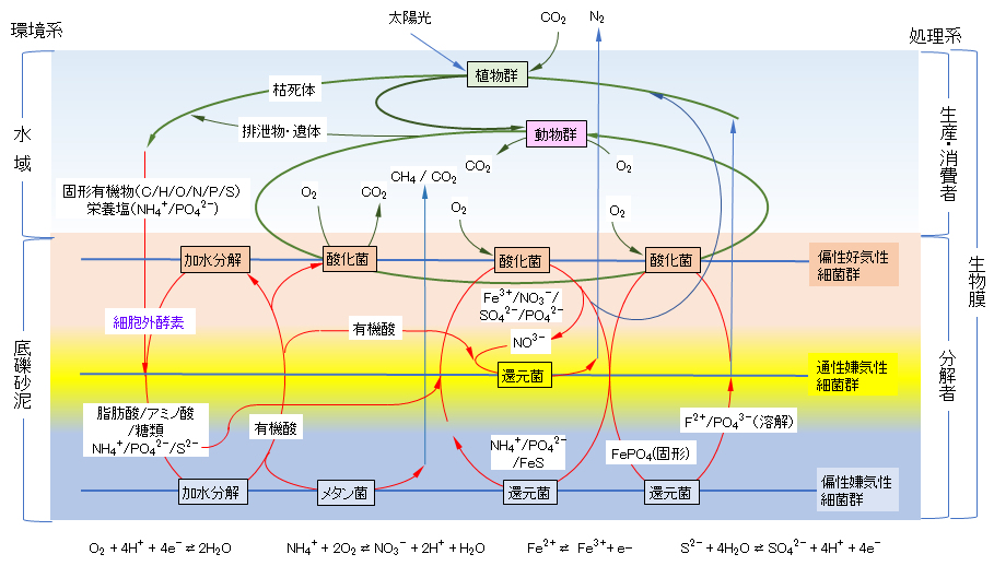
図1 自然界における生態系による物質循環と生物膜の理解モデル
Fig.1. Model for understanding material cycle and biofilm by ecosystem in the natural world.
(3)生物膜法の工学的利用
自然界には細菌類は好気性、通性嫌気性および偏性嫌気性がその環境条件に対応して生存するが、水浄化においては工学的にその環境を制御してバランス良く細菌類を選別して、それぞれの汚濁物質を汚水から取り除く方法が採用される。
(3) Engineering use of biofilm method
In the natural world, bacteria survive aerobic, facultative anaerobic and obligate anaerobic in response to their environmental conditions, but in water purification, the environment is engineered to control the environment in a well-balanced manner. Then, the method of removing each pollutant from wastewater is adopted.
1) 生物膜法の特徴
水浄化に細菌類を利用する方法には、1) 細菌類を水中に懸濁状態で利用する浮遊法と2)本ページで扱う個体表面に付着・保持して利用する生物膜法がある。
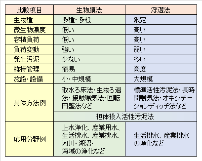
懸濁法に対する生物膜を比較すると(表1)、有効容積中の微生物量が少ないが、負荷変動に対して強く、発生する汚泥量が少なく、維持管理が簡易であることである。
微生物量が少ないのは、浮遊法が水空間全体を利用しているのに対して、生物膜法は表面積または担体間空隙を利用するからである。流入水量や負荷変動に対して強く安定しているのは、微生物群が固定化されているからである。ただし、過大な負荷に対して処理水質が安定していることではない。発生する汚泥が少ないのは、多種多様な生物からなる生態系が形成され、増殖した微生物が他の生物によって捕食されるからである。
維持管理が簡易なことから、国内では、戸建て住宅の家庭排水の浄化槽など、専任要員がいない中小浄化設備などに利用されている(4.(2)に記載)。
1) Features of the biofilm method
Methods for utilizing bacteria for water purification include 1) a suspension method in which bacteria are used in a suspended state in water, and 2) a biofilm method in which the bacteria are retained on the solid surface described on this page.
Comparing biofilms to the suspension method (Table 1), the amount of microorganisms in the effective volume is small, but it is resistant to load fluctuations, the amount of sludge generated is small, and maintenance is easy.
The low microbial load per an unite device volume is due to that the biofilm method utilizes surface area or inter-carrier voids (or spaces), whereas the suspension method utilizing the entire water space resulting in high load availability. But, the biofilm method is strongly stable against changes in water inflow and polutant load because the microbial community is immobilized. It does not mean that the treated water quality is stable against excessive loads. The amount of sludge generated is small because an ecosystem consisting of a wide variety of organisms is formed and the proliferated microorganisms are eaten by other organisms.
Since the biofilm system is easy to maintain and manage and used at domestic small-medium purification facilities such as on site septic tanks for domestic wastewater at detached houses[Described in 4.(2)], etc.
Table 1 Comparison of biofilm method and suspension method in water purification.
2) 生物膜法の分類
生物膜利用法には、細菌類の生息条件の視点から、1)好気条件に制御して汚水中の有機物を炭酸ガスへ変換する方法、2)無酸素条件で結合性酸素で呼吸する細菌類を利用して窒素ガスへ変換する方法と、3)絶対(偏性)嫌気条件下で固形物の加水分解・溶解する細菌群と溶解した物質をメタン・炭酸ガスへ変換する方法に大別される。
工学・土木的な視点からの生物膜利用法は、1)反応槽(池)内に生物膜を保持して汚水を浄化する分野と2)河川・湖沼・海域などに浄化システムを構築して水域を浄化する分野に大別される。
微生物を保持する固体を担体と称することが多いが、利用する方法や分野によって充填材、接触材、ろ材などどとも呼ばれている。また、担体を構成(充填)する部分を担体床、接触床またはろ床などという。
さらに、微生物担体を装置内に1)固定床法と、2)反応槽内に流動させる流動床法がある。
以上述べたように、生物膜法には多種多様な方式があり、単一装置あるいは他方法と組み合わせた複合システムとして、様々な水浄化分野で広く活用されている。
2) Classification of biofilm method
The viewpoint of conditions for the bacteria classfies biofilum methods: 1) a method of converting organic matters in wastewater into carbon dioxide by keeping aerobic conditions, 2) another using bacteria which breathe with bound oxygen under anoxic (oblique) conditions to convert nitrogen oxide compounds to nitrogen gas, and 3) the last using a group of bacteria under absolute anaerobic conditions which hydrolyzes/dissolves organic solids and converts the dissolved organic matters to methane and carbon dioxide.
From the viewpoint of process and civil engineerings, the methods of using biofilm are as follows: 1) Retaining a biofilm in a reaction tank (pond) to purify wastewater, and 2) constructing a purification system in rivers, lakes and seas.
Although solids that retain microorganisms are often called carriers, they are also called fillers, contact materials, filter media, etc. depending on the method and field of use. In addition, a portion constituting (filling) the carrier is referred to as a carrier bed, a contact bed or a filter bed.
Further, there are 1) a fixed bed method in which the microbial carrier is placed in the apparatus and 2) a fluidized bed method in which the microbial carrier is fluidized in the reaction tank.
As mentioned above, there are various types of biofilm methods as a single unit device and as the compex system including the filter unit, and they are widely used in various water purification fields.
2.生物膜法の反応槽
一般的に、大量の水を処理する上水や下水の処理施設では広大な面積を占めるので、国内では水を処理する単位設備を池(pond)といい、少・中量の水を処理する単位設備は槽(tank)といわれる。ここでは、特に断らない限り、池も槽で表示する。ここでは、その付帯設備(空気・酸素を供給する設備、水位計と流入・放流・循環等のポンプ類、増殖汚泥の引き抜き、生物膜の剝離・洗浄などの設備など)を含めて反応槽と表示する。
2. Biofilm reactor
Generally, in Japan, the water and sewage treatment facilities, those treat large amounts of water, occupy a vast area and so the unit equipment is called pond. The unit equipment that processes some amount of water is called tank. Unless otherwise specified, both tank and pond are decribed here as reaction tank or reactor which include the auxiliary equipments (units supplying air/oxygen, water flow/level gauges, pumps for inflow/outflow/circulation, extraction unit of excess sludge, separation/washing unit of biofilm, etc.)
(1)反応槽の方式と種類
反応槽の方式と種類を図2に示す。まず、反応槽は、散水型(A)と浸漬型に分類される。散水型は担体が大気と接触し、浸漬型は担体が全て水中に浸漬している。浸漬型は固定床型(B)と流動床型(C)に分けられる。流動床では、担体が槽内で自由に流動して、汚水と接触させている。
固定床型はさらに上向流型と下降流型がある。また、固定床には多層型(D)や密封型(E)があり、密封型ではろ床の圧力損失を計測する圧力計または外接した水頭差計を取付けて、運転や担体洗浄を適切に実施する。
密封型は、設置面積・空間が狭い浄水設備として利用される(最大圧力損失は、通常、1~2mの水圧に設定されることが多い)。
多層型では比重の異なる担体を充填して、各担体層を分けることが多いが、異なる性状の担体を支持体で保持・分層する反応槽も用いられている。
以下、代表的な生物膜法について紹介する。
(1) Method and type of reactor
The system and type of reaction tank are shown in Fig.2. First, the reaction tank is classified into a water sprinkling type (A) and an immersion type. In the sprinkling type, the carrier is in contact with the atmosphere, and in the immersion type, the carrier is entirely immersed in water. Immersion type is divided into fixed bed type (B) and fluidized bed type (C). In a fluidized bed, the carrier is free flowing in the tank and is in contact with wastewater.
The fixed bed type is further classified into an upflow type and a downflow type. In addition, there are multi-layer type (D) and sealed type (E) among the fixed bed reactors, and in the sealed type, a pressure gauge for measuring the pressure loss of the filter bed or an external head difference gauge is attached to properly operate and wash the carrier. The sealed type is used as a water purification facility with a small installation area and space (the maximum pressure loss is usually set to 1 to 2 m of water pressure).
In the case of the multi-layer type, carriers having different specific gravities are often filled to separate each carrier layer, but a reaction tank in which carriers having different properties are held/separated by a support is also used.
The representative biofilm methods are shown in the figures below.
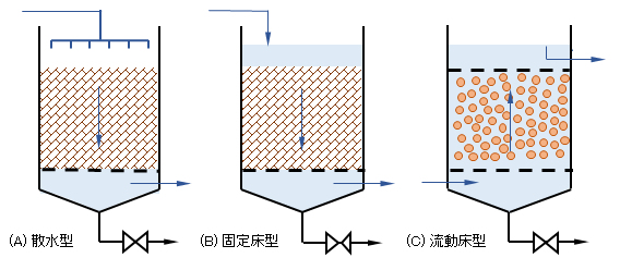
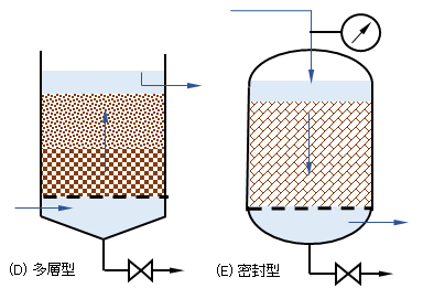
図2 生物膜法の反応槽形式
Fig.2 Reactor type of biofilm method:
(A) water sprinkling, (b) fixed bed, (C) fluidized bed,(D) multi-layer bed, and (E) sealed reactor.
(2)散水ろ床法
散水ろ床法では、担体を詰めたろ床の上から散水し、担体表面に付着した微生物によって浄化する。酸素はろ床の下から、空気の自然対流によって供給される。担体は、以前には石・礫が利用されたが、現在では軽くて比表面積の大きい多様な形状のプラスチックが用いられている。維持管理が容易で省エネルギーである。散水装置はろ床に対して均一に汚水を散水することで、代表的なものとして回転式散水法がある。
一方で、ハエや異臭の発生、季節の変わり目に生物膜の脱落、処理水の泡立ち、懸濁物質の増加など、水質が悪化することがある。
この方法は今日のわが国ではほとんど採用されていないが、簡易な方法であり、国際的には地域の状況によって有効な方法である。
(2) Sprinkling filter method
In the sprinkling filter method, water is sprinkled on a filter bed packed with a carrier and purified by microorganisms adhering to the surface of the carrier. Oxygen is supplied from below the filter bed by natural convection of air. Previously, stones and gravel were used as the carrier, but nowadays, various shapes of plastics that are light and have a large specific surface area are used. It is easy to maintain and save energy. The water sprinkler sprays filthy water uniformly on the filter bed, and a typical method is the rotary water sprinkling method.
On the other hand, the quality of water may be deteriorated due to the generation of flies and offensive odors, the loss of biofilm at the change of seasons, the bubbling of treated water, and the increase of suspended solids.
Although this method is rarely adopted in Japan today, it is a simple method and is internationally effective depending on the local situation.
(3)接触曝気法
接触曝気法は、ろ床(接触床)が全て汚水中に浸漬している固定型で、酸素を供給する設備が必要となる。なお、本法に類似した絶対嫌気性接触法では、反応槽は密封され酸素の溶解を阻止し、汚水をろ床へ通水する。脱窒素システムでは、ろ床を無酸素状態にして通水し、亜・硝酸イオンを窒素分子へ還元する。
酸素供給は、反応槽内の空間へ空気を散気して酸素を溶解するとともに、そのエアリフト効果により汚水を攪拌または循環してろ床内の担体と接触させている。図3に示すように、全面曝気、側面曝気、中心曝気の3つ方法がある。ろ床が大きくなると、汚水と担体との接触が不均一となるので、反応槽を仕切るかまたは反応槽を複数設置して汚水を分配・流入し、汚水と担体との均一な接触を行う。ろ床の縦:横は1:1~3とすることが一般的である。
中央型と側面型には、同図の平面図に示すようの空隙も円筒型(A)、楕円筒型(B)、板で仕切った型(CやD)などがある。
担体洗浄用の曝気装置を取り付ける場合には、(C)と(D)のようなタイプが補修や配管内洗浄などでの取り外しに適している。(A)のようなタイプは、反応槽内の担体の充填率を高くとることができるが、ろ材底部の附帯設備の管理が難しく、上部からのジェット水流などで生物膜の剥離ができる担体あるいは逆洗により容易に流動状態となる担体に適している。
接触曝気型では、肥大化した生物膜の剝離片が処理水中に混在するので、後段に沈殿槽が必要となる。代表的な適用例は、生活排水を処理する小中型の浄化槽である。
(3) Contact aeration method
The contact aeration method is a fixed type in which the filter bed (contact bed) is entirely immersed in waste water, and equipment for supplying oxygen is required. In the absolute anaerobic contact method similar to the method above, the reaction tank is sealed to prevent the dissolution of oxygen, and waste water is passed through the filter bed. In the denitrification system, the filter bed is anoxic and water is passed through to reduce nitrite/nitrite ions into nitrogen molecules.
For oxygen supply, air is diffused into the space in the reaction tank to dissolve oxygen, and the airlift effect causes the wastewater to stir or circulate to bring it into contact with the carrier in the filter bed. As shown in Fig.3, there are three methods of full aeration, side aeration, and central aeration. When the filter bed becomes large, the contact between the wastewater and the carrier becomes uneven. Therefore, the reaction tank is partitioned or a plurality of reaction tanks are installed to distribute and inflow the wastewater, and the wastewater and the carrier are uniformly contacted. It is general that the length : width of the filter bed is 1 : 1 to 3.
As shown in the plan view of the figure, the central type and the side type also have a void, cylindrical type (A), an elliptic cylindrical type (B), or a plate-divided type (C and D).
When installing an aerator for cleaning the carrier, the types (C) and (D) are suitable for removal during repairs or cleaning inside pipes. The type such as (A) can make the packing rate of the carrier in the reaction tank high, but it is difficult to manage the auxiliary equipment at the bottom of the filter medium, and the carrier that can separate the biofilm by jet water flow from the top or it is suitable for a carrier that is easily fluidized by backwashing.
In the contact aeration type, since the separated pieces of the enlarged biofilm are mixed in the purifed water, a sedimentation tank is required in the latter stage. A typical application example is a small-medium-sized septic tank that treats domestic wastewater (see Fig.11 below).
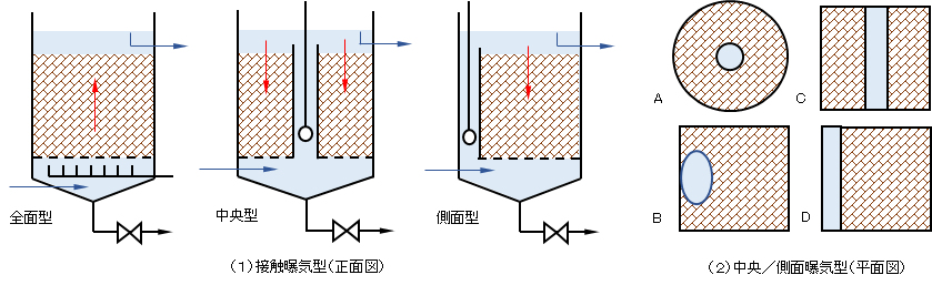
図3 接触曝気法における酸素供給と循環接触
Fig.3 Oxygen supply and circulating contact in the contact aeration method
全面曝気型 full aeration, 中央曝気型 side aeration, 側面曝気型 central aeration.
正面図 vertical cross section, 平面図 horizontal cross section.
(4)生物ろ過法
固形物質の捕捉と溶解物質の分解機能を兼ねた浄化システムで、空隙率の少ないろ床とし、粒状または小サイズ中空状の担体を利用することが多い。固形物・溶解性を含めて汚濁物質濃度が低い用水・汚水の浄化に利用される。後段の沈殿槽は特別な場合を除き、付設されない。
担体が数mm以上のものは、観賞・養殖・活魚などの魚の水槽の水浄化に利用されている。浄水場の緩速砂ろ過では、有効径0.5~0.7mm、均等係数1.7以下の砂が用いられる。サイズの小さい担体を導入したろ床では、その圧力損失が高く曝気循環の効率が悪い場合には、外部で散気して酸素を含む汚水を反応槽へ流入・循環させる(図4の外部型)。
(4) Biological filtration method
It is a purification system that has the functions of capturing solid substances and decomposing dissolved substances, and often uses a granular or small size hollow carrier as a filter bed materials with a low porosity. It is used to purify water and wastewater with low concentrations of pollutants including both solid and soluble. The latter settling tank is not attached except for special cases.
Carriers with a diameter of several mm or more are used for water purification in aquariums for ornamental, aquaculture and live fish. For slow sand filtration at water treatment plants, sand with an effective diameter of 0.5 to 0.7 mm and a uniform coefficient of 1.7 or less is used. When the pressure loss is high and the efficiency of aeration circulation is low in a filter bed with a small size carrier used, the wastewater containing oxygen is inflowed and circulated through the reaction tank (see the external aeration in Fig.4).
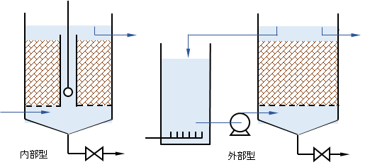
図4 生物ろ過法の酸素供給と循環接触
Fig.4 Oxygen supply and circulation contact of biological filtration method.
内部型:internal aeration, 外部型:external aeration
(5)回転円盤法
本体の中心軸に多数の軽量で強固な円板体(径3~5m)を一定間隔ごとに多数枚固定(基本構成)し、反遠藤形状の接触反応槽に円板表面積の40%程度を浸漬させ(図5)、駆動装置により、円板の外周速度20m/分以下で低速回転させる。水量と汚濁成分によって、上記基本構成を単独、あるいは複数を直列または並列に組み合わせてシステムを構成する。後段に剝離汚泥等を除去する分離槽が必要である。
(5) Rotating disk method
A large number of lightweight and strong discs (diameter 3 to 5m) are fixed to the center axis of the main body at regular intervals (basic configuration), and approximately 40% of the disc surface area is provided in the anti-endo type contact reaction tank. It is dipped (Fig.5) and rotated at a low speed at a peripheral speed of the disk of 20 m/min or less by a driving device. Depending on the amounts of wastewater and pollutant, the above basic configurations may be used alone, or a plurality of them may be combined in series or in parallel to form a system. A separation tank for removing sludge and the like is required at the latter stage.
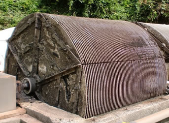
図5 回転円盤法の事例 Fig.5 Example of Rotating disk method
引用資料 Material cited: 三鈴工業 Misuzu Industry
(6)流動床法
比重が水と等しく、汚水とともに自由に流動する担体を利用する反応槽(嫌気槽では攪拌のみ、好気槽では曝気攪拌)で、担体の表面・内部に微生物群を保持して汚水を浄化する(図2(C))。
一般的には数~数10mmの中空円筒状、骨格球状、粒状またはスポンジ状などの担体を、反応槽の10~30%程度充填する。処理水の流出側にはスクリーンを設置して、担体が槽内部へ保持される。また、固定したスクリーン枠内で流動させる方式もある。
担体表面の生物膜は、担体同士の衝突・接触により、剝離されて適切な膜厚に更新される。また、担体内部では、微生物は滞留日数が長く保たれ、硝化菌などの増殖速度の遅い細菌群が保持できる。一般的には、後段に汚泥分離装置が付設される。
(6) Fluidized bed method
A reaction tank that uses a carrier that has some same specific gravity as water and that freely flows with wastewater (only agitating in an anaerobic tank, aeration stirring in an aerobic tank) holds microorganisms on the surface and inside the carrier to purify wastewater. (Fig.2(C)).
Generally, a hollow cylindrical, skeletal spherical, granular or sponge-like (see Photos 1 and 2 below.) carrier having a diameter of several to several tens of mm is filled in about 10 to 30% of the reaction tank. A screen is installed on the outflow side of the treated water to hold the carrier inside the tank. In addition, there is also a method of fluidizing the wastewater in a fixed screen frame.
The biofilm on the surface of the carrier is peeleded by the collision/contact between the carriers and renewed to have an appropriate film thickness. In addition, inside the carrier, the number of days of retention of the microorganisms is kept long, and bacteria having a slow growth rate such as nitrifying bacteria can be retained. Generally, a sludge separator is attached at the latter stage.
活性汚泥法の効率向上
本法は、既設の活性汚泥法へ適用すると、反応槽内の微生物量を増大させて処理効率を高めたり、また、浮遊性微生物群と異なる微生物群(例えば、増殖速度の遅いものを)を担体に保持させ、特殊な機能を付加することができる。
また、既設の処理施設に対し、状況変化により負荷が当初の計画より増加あるいは減少した場合や新たな機能を付加する場合に、本法の導入においては、処理水流出部分にストレーナー等を付設するだけで、既存施設の改修や増設をしなくても対応が可能となる。
Improved efficiency of activated sludge method
This method is often applied to the existing activated sludge method to increase the amount of microorganisms in the reaction tank to improve the treatment efficiency, and it is possible to use a special microorganism group (for example, one with a slow growth rate) different from the general group. It can be held on a carrier to add a special function.
In addition, when the load on the existing treatment facility increases or decreases from the original plan due to changes in the situation or a new function is added, a strainer etc. will be attached to the treated water outflow part when introducing this method.
Only by doing so, it is possible to deal with the situation without modifying or expanding existing facilities.
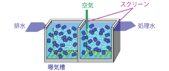
図6 流動担体型型活性汚泥法
Fig.6 Fluidized carrier type activated sludge process.
引用資料 Matrial cited: 化工機プラント 環境プラント Kakoki Plant & Environment Engineering.
(7)生物膜の洗浄・再生
担体に付着した生物膜は、微生物の増殖により肥大する。ろ床に部分的あるいは全面的に閉塞が起こり、担体に付着した生物群との接触が不十分となり、浄化能力が低下する。担体に付着した生物物膜を剝離・除去することをろ床の洗浄または再生という。また、ろ床への通水方向を逆転して洗浄・再生する場合には逆洗という。洗浄・再生の方法を問わず、逆洗ということもある。
洗浄法には、手作業による方法、自動的に行う方法、また、一定間隔や連続的に行う方法などに分類される(図7)。これらの方法の選定は、担体や反応槽の種類・形式や維持管理体制により異なる。
一般的には、稼働時より速い流速の洗浄水またはろ床への直接曝気等により 1) 担体を流動状態にする方法と 2) 固定された担体表面から直接剝離する。また、3) 反応槽内の汚水を引き抜いて手作業による水道水のジェット水流により生物膜を直接剝離する方法では、ろ床底部まで洗浄水が届く形状の担体(図7(A))に限定される。
4) 連続洗浄法では、均一粒径率の高い砂など、流動性・耐摩耗性の高い担体に適用される。洗浄後の濁りが発生することなく、低い一定のろ過抵抗で安定した良質のろ過水が連続的に得られる。この方法は生物膜法というより物理的なろ過に分類されるが、メタノール添加により脱窒素機能を有するなど生物機能を付加することが可能となる。連続洗浄法の代表的なものに移床式上向流連続砂ろ過がある(図7(D)参照)。
(7) Cleaning and regeneration of biofilm
The biofilm attached to the carrier grows due to the growth of microorganisms. The filter bed is partially or wholly clogged, resulting in inadequate contact of water with the organisms adhering to the carrier and a reduction in purification ability. Separation and removal of the biological film attached to the carrier is called washing or regeneration of the filter bed. In addition, backwashing is used when washing and regeneration are performed by reversing the direction of water flow through the filter bed. It may be called backwash regardless of the method of cleaning and regeneration.
The cleaning method is classified into a manual method, an automatic method, a constant interval method and a continuous method (Fig.7). The selection of these methods depends on the types and formats of carriers and reaction vessels and the maintenance system.
Generally, 1) a method of bringing the carrier into a fluidized state by direct aeration of wastewater from the bed botom or by a water flow through the filter bed at a flow velocity faster than during operation, and 2) separating the carrier directly from the fixed carrier surface. Further, 3) In the method in which the waste water in the reaction tank is drawn out and the biofilm is directly separated by the jet stream of tap water by manual work, it is limited to the carrier bed such as shown in Fig.7(A) having a shape that allows the wash water to reach the bottom of the filter bed.
4) The continuous washing method is applied to carriers with high fluidity and abrasion resistance, such as sand with a high uniform particle size ratio. Stable and good quality filtered water can be continuously obtained with low constant filtration resistance without generating turbidity after washing. This method is classified as a physical filtration bed rather than a biofilm method, but it becomes possible to add a biological function such as having a denitrification function by adding methanol. A typical continuous washing method is a bed transfer type upflow continuous sand filtration (see Fig.7(D).).
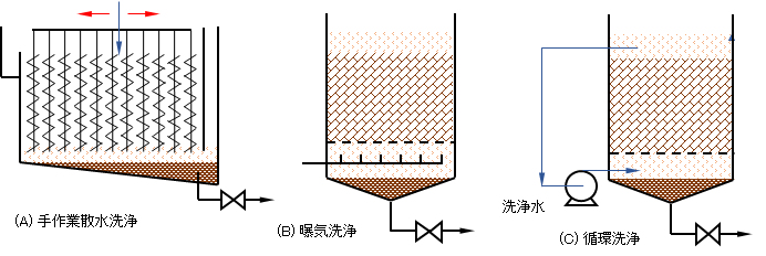
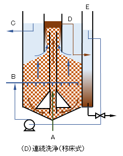
図7 生物膜の洗浄・再生
Fig.7 Biofilm cleaning and regeneration.
Wshing the fiter bed: (A) Regularly manual work, (B) Regularly aeartion, (C) Regular reverse circulation, (D) Continuous cleaning, (B) and(C) is possible to operaste automatically.
3.担体の種類と選定
担体の種類と選定には、生物膜法を用いた反応槽の方式と深く関係する。特に、反応槽の方式として1) 散水ろ床法・2) 接触曝気法・3) 生物ろ過法・4) 流動床法では、利用目的が異なり選定する担体も大きく異なる。また、方式2)~4)を同一の反応槽に組み込み、加えて好気・嫌気条件も異なる複雑な浄化システムも多数ある。いずれの方式・システムにおいても、必須の共通事項は、肥大化した生物膜の剝離(洗浄・逆洗)をどのような方法で行うかによって、選定する担体も異なることである。
3. Type and selection of carrier
The type and selection of the carrier are closely related to the reactor system using the biofilm method. In particular, in the 1) sprinkling filter method, 2) contact aeration method, 3) biological filtration method, and 4) fluidized bed method, the purpose of use differs and the carrier to be selected also greatly differs. In addition, there are many complicated purification systems in which methods 2) to 4) are installed in the same reactor system and aerobic and anaerobic conditions are different. Whatever any methods/systems are used, the essential common matter is that the carrier, to be selected, also differs depending on the separating method for the enlarged biofilm (by washing or backwashing).
(1)材質による分類
担体は、1)天然品か 2)合成品か、また材質からは無機質か有機質かに大別される。
無機質には 1)に属する砂・礫・石・アンスラサイト(無煙炭を破砕したもの)・死骸サンゴ、2)に属するセラミック(焼成品)・ゼオライトなどがある。有機質には1)に属するシュロ(ヤシ科植物の皮)・ヨシなどの繊維質など、2)に属するプラスチック・合成繊維などがある。
環境水(河川・湖沼・海域など)浄化では、水草・海藻・水辺植物の茎・浮草の根から底泥表層部・砂・礫などが自然にあるもの、これらを模した人工製造品も多数利用されている。
(1) Classification by material
Carriers are roughly classified into 1) natural products and 2) synthetic products, and depending on the material, inorganic or organic.
Inorganic substances include sand, gravel, stones, anthracite (crushed anthracite), coral carcasses belonging to 1), and ceramics (calcined products) and zeolite belonging to 2). Organic substances include palm (skin of coconut plants) and reeds that belong to 1), and plastics and synthetic fibers that belong to 2).
In the purification of environmental water (rivers, lakes, seas, etc.), there are naturally aquatic plants, seaweeds, stalks of waterside plants, roots of bottom mud surface, sand and gravel, and many artificial products that imitate these have been done.
(2)形状による分類
粒状、球・楕円体状、立方・長方体状、板状(凹凸や波形)、布状、糸状、円筒状、格子状、多孔状など、また、これらの形状を立体的に組み合わせた形状が多い(図8)。流動ろ床においては、粒状やスポンジ状の担体が使用される。板状のものを立体的に組み合わせた担体は、適切なサイズにカットして反応槽に直接取り付けることができる。
(2) Classification by shape
Granular, spherical/ellipsoidal, cubic/rectangular, plate-like (uneven or corrugated), cloth-like, thread-like, cylinder-like, lattice-like, porous, etc., or a combination of these shapes in three dimensions. (Fig.8). In a fluidized bed, granular or sponge-like carriers are used. The carrier in which the plate-like materials are three-dimensionally combined can be cut into an appropriate size and directly attached to the reaction tank.
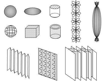
図8 担体の形状の事例
Fig.8 Example of carrier shape.
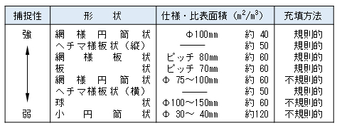
Table 2 Shapes of general carriers used for anaerobic filter beds in septic tanks [Nikkan Kyoiku Center, 2017]
(3)比重による分類
比重は反応槽に充填うる担体には、沈降性、浮上性または流動性の3つに分けられる。
固定型ろ床においては、板状・格子状で固定された担体を除き、沈降性または浮上性の担体おいては稼働時(特に上向流型)には固定状態である。逆洗や曝気による担体の洗浄においては流動状態となる比重(サイズによって異なる)が求められる。流動床に用いる担体では、水の流動に対応して自由に流動できる比重が求められる。
また、多層ろ床では比重差(沈降速度差はサイズと比重に関係する)により分層するか、メッシュ状のストレーナ枠に保持した異なるろ床で分層する。水流によって分層する多層ろ床では、担体の比重(サイズを含めて)が選定条件となる。
(3) Classification by specific gravity
The specific gravity of the carrier that can be filled in the reaction tank is divided into three types: sedimentation, floatability and fluidity.
In a fixed-type filter bed, except for a carrier fixed in a plate-like or lattice-like form, a settling or floating carrier is in a stationary state during operation (in particular, an upflow type). In backwashing or washing the carrier by aeration, the specific gravity (depending on the size) is required for the carrier to be in a fluidized state. The carrier used for the fluidized bed is required to have a specific gravity that allows it to freely flow in accordance with the flow of water.
Further, in the multi-layer filter bed, the layers are separated by the difference in specific gravity (the difference in settling velocity is related to the size and the specific gravity), or the layers are separated by different filter beds held in a mesh strainer frame. In the case of a multi-layer filter that is separated by a water flow, the specific gravity (including size) of the carrier is a selection inex.
(4)サイズによる分類
水浄化の目的・用途により、担体はその形状のサイズが選別の重要な要素となる。
形状によっては、担体サイズとその機能に大きな相関はないが、空隙率の低い砂など粒状の担体はそのサイズ(均等率を含む)と機能の相関性が高い。例えば、上水の浄化では懸濁物質の除去に緩速ろ過がある。これは5m/日(= 25cm/時間)の流速で通水する。この機能は、沈降分離池で除去できない微細粒子を捕捉するとともに、ろ床上部に生息する原生動物が捕捉粒子を摂取して有機物を分解している。また、比重の大きい礫・石などは、生物膜の洗浄・再生が難しくなる。また、円筒形の担体はサイズが小さくなると、筒内に生物膜が充満し、その洗浄・再生法が困難となる。
機能が異なる担体をストレーナー等で分層する反応槽内にあっては、支持体内部に逆洗展開率(下記3.(6) 5)を参照)を満たす空間を設けるなど、洗浄・再生が可能な構造とする。
(4) Classification by size
Depending on the purpose and use of water purification, the size of the carrier is an important factor for selection.
Depending on the shape, there is no significant correlation between the carrier size and its function, but a granular carrier such as sand with a low porosity has a high correlation between its size (including the even ratio) and its function. For example, in the water purification for tap water, slow filtration is used to remove suspended substances. It passes through at a flow rate of 5 m/day (= 25 cm/hour). This function captures fine particles that cannot be removed in the settling pond or tank, and protozoa inhabiting the upper part of the filter bed ingest the captured particles to decompose soluble organic matter. It is difficult to clean and regenerate the biofilm for gravel and stones that have a large specific gravity. In addition, when the size of the cylindrical carrier is reduced, the cylinder is filled with the biofilm, which makes it more difficult to wash and regenerate the carrier.
In a reaction tank in which carriers having different functions are separated by a strainer or the like, a structure capable of cleaning and regeneration is provided by making a space inside the support frame that satisfies the backwash blanket rate (see 3.(6) 5)) below).
(5)ろ床の支持体
担体を保持する支持体には、1)ろ床の水平面全体に対し均等に流入・流出させる機能、2)担体がろ床外へ流出しない機能、3)逆洗に支障のない構造(大きいサイズの担体の曝気洗浄など)、4)荷重に耐える強度(担体比重の大きいもの、ろ過抵抗が大きいものなど)、5)支持体通過での圧力損失の低いもの(砂・ビーズなど、サイズの小さい担体の支持体)などが求められる。ろ床の水平面が広くなる場合には、支持体をブロック化するなど、上記1)から5)の要件を満たすような構造とする。
前述2)の項目については、担体充填槽の流入部・流出部や逆洗水の取水部などに、担体より目幅の小さいスリットやメッシュ状の担体受けや押さえが設置されることとなる。担体受け・押さえの部分では閉塞の可能性が高くなるので、設計・維持管理において留意する。担体サイズが特に小さい生物ろ過では、ストレーナーなどが取り付けられる。
(5) Filter bed support
The support which holds the carrier should satisfy the items; 1) a function that allows the carrier for water to flow in and out uniformly toward the entire horizontal section of the filter bed, 2) a function that the carrier does not flow out of the filter bed, and 3) a structure that does not hinder backwashing (especially, for aeration cleaning of the carrier of large size), 4) strength to withstand load (high specific gravity of the carrier, high filtration resistance, etc.), and 5) low pressure loss through the support (especially, for small size carriers such as sand, beads, etc.). When the horizontal surface area of the filter bed becomes wider, the structure shall be made such that the support is blocked so as to meet the above requirements 1) to 5).
Regarding the item 2), slits or mesh-shaped carrier receivers and retainers having a smaller mesh size than the carrier are installed at the inflow/outflow parts of the carrier filling tank. Since there is a high possibility of blockage at the part that receives and holds the carrier, be careful in design and maintenance. For biological filtration where the carrier size is particularly small, strainers and the like are attached.
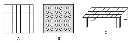
図9 担体支持体の事例 Fig.9 Example of carrier support
(6) Carrier selection index
1) Filling rate of filter bed
The filter bed volume (regardless of fixed or fluid) occupying the effective volume of the reaction tank is called the carrier filling rate [%].
2)担体ろ床内の空隙率
ろ床容積に占める空間容積を空隙率といい、ろ床容積に占める水量 [m3/m3] でほぼ表すことができる。具体的には、水を満たした水槽に一定容積の担体を入れ、増加した水量で求める方法、あるいは空の水槽に一定容積の担体を充填し、担体上部表面まで水を満たして、その水量から空隙量を求めることができる。空隙率はろ床内に保持する生物量と処理性能に大きく影響するが、担体の洗浄・再生の方法やその間隔の日数・回数などの維持管理の面から選定する。
2) Space rate in carrier filter bed
The space volume that occupies the filter bed volume is called the space(or void) rate, and can be almost expressed by the amount of water [m3/m3] that occupies the filter bed volume. Specifically, the amount of space can be calculated by either method in which a fixed volume of carrier is placed in a water tank filled with water and the amount of water is increased, or an empty water tank is filled with a fixed volume of carrier and water is filled up to the upper surface of the carrier. The space rate has a great influence on the amount of organisms retained in the filter bed and the treatment performance, but it is selected from the viewpoint of the method of washing the carrier and the maintenance such as the number of the operation intervals.
3)担体の比表面積
流動水が接触できる担体の面積で、比表面積とは単位容積当たりの担体の表面積 [m2/m3] で表すことができる。活性炭は分子 (10-10mレベルのサイズ) を吸着し、ミクロポア(10-9mレベル)やマクロポア(10-6mレベル)を含めて表面積を表す。生物膜担体では付着する細菌類は10-6mレベルであるので、活性炭などの化学物質吸着材の表面積 [m3/kg] とは異なることに留意する。マクロポアやミクロポアを有する多孔質担体も広く用いられているが、主として製造過程で担体比重を制御している。
3) Specific surface area of carrier
The surface area of the carrier that can come into contact with flowing water, and the specific surface area can be expressed as the surface area of the carrier per unit volume [m2/m3]. Activated carbon adsorbs molecules (size of 10-10m level), and micropores (10-9m level) and macropores (10-6m level) is included to express the surface area. Note that bacteria attached to biofilm carriers are at some level of 10-6m, which is different from the surface area [m3/kg] of adsorbents for chemical substances such as activated carbon. Porous carriers having macropores or micropores are also widely used, but the carrier specific gravity is mainly controlled in the production process to ajust the surface area.
4)担体の摩耗性
担体は肥大化した生物膜を剝離するための洗浄が定期的に行われるので、破砕、剥がれ、千切れなどにより担体が消耗するので定期的な補充が必要となり、耐摩耗性の担体が望まれる。特に、流動床では常に衝突・接触が起こるので、担体の耐摩耗性が重要な要素となる。
4) Carrier wear
Since the carrier is regularly washed to separate the enlarged biofilm, the carrier is consumed due to crushing, peeling, tearing, etc., so periodical replenishment is required, and a wear-resistant carrier is desired. Particularly, in a fluidized bed, collision and contact always occur, so that the wear resistance of the carrier is an important factor.
5)逆洗展開率
逆洗を行う場合、洗浄水の水量が少ないほど、抜取り汚泥の処理・処分の手間・経費が削減される。逆洗により担体が流動状態となる容積のろ床容積に対する増加率 [%] で示す。逆洗展開率が低いほど、洗浄水が少量となる。また、洗浄水の流速>沈降(また浮上)速度で流動状態となるので、展開率は担体の比重・サイズと洗水の速度・粘度(水温)に依存することとなる。
5) Backwash blanket rate
For backwashing, the smaller the amount of wash water, the less labor and cost for treating and disposing of the extracted sludge. It is indicated by the rate of increase [%] of the volume of the carrier blanket that becomes fluidized by back-washing with respect to the filter bed volume. The lower the backwash blanket rate, the smaller the amount of wash water. Further, since the flow state of the wash water > the settling (or floating) velosity, the fluidized state depends on the specific gravity/size of the carrier and the velosity/viscosity (water temperature) of the wash water.
6)担体への生物膜の付着性
細菌類の担体表面への付着性は、細菌類の好気・嫌気性やその生物群、汚水成分とその濃度、淡水・海水、温度など様々な要因によって異なる。付着性の弱い細菌類では、担体空隙率、フロック生成能、担体表面の性状(微細な凹凸、繊毛、表面電荷、親水・疎水性など)が要因となる。
生物膜の付着性は、稼働中は担体表面に保持され、肥大化した生物膜は逆洗等の簡便な操作で剝離・除去されるように、適度な付着力が求められる。前述したように、生物膜の付着力は担体表面の性質や形状に大きく依存するので、選定において重要な条件となる。
活性汚泥法の効率向上の目的で、流動性担体の中には、通常の有機物の酸化細菌群と硝化菌群の担体への付着性の差異を利用して、硝化菌群を選択的に付着させる担体も開発されている。
なお、空隙率の低いろ床では、担体表面や担体細孔に付着するというより微生物フロックが担体粒子間の空隙に保持される傾向が高い。
6) Adhesion of biofilm to carrier
The adherence of bacteria to the carrier surface depends on various factors such as aerobic and anaerobic bacteria, their organisms, wastewater components and their concentrations, freshwater/seawater, and temperature. For bacteria with weak adherence, the carrier porosity, floc-forming ability, and carrier surface properties (fine irregularities, cilia, surface charge, hydrophilicity/hydrophobicity, etc.) are factors.
The adhesiveness of the biofilm is required to be appropriate so that the biofilm is retained on the surface of the carrier during operation and the enlarged biofilm is detached and removed by a simple operation such as backwashing. As described above, the adhesive force of the biofilm depends largely on the properties and shape of the surface of the carrier, which is an important index for selection.
For the purpose of improving the efficiency of the activated sludge method, specified carriers have also been developed among the carriers that are easily fluidized. The nitrifying bacteria group is selected by utilizing the difference in the adhesiveness of ordinary organic carriers between the oxidizing bacteria group and nitrifying bacteria group.
In addition, in a filter bed with a low void rate, microbial flocs are more likely to be retained in the voids between the carrier particles rather than being attached to the carrier surface and/or inside pores.
4.生物膜法を利用した水浄化事例
(1)水道水-緩速ろ過
浄水場では、原水中の砂除去(図10-②)、凝集沈殿による懸濁物の除去(④)、微細粒子のろ過除去(⑤)、消毒剤(塩素)を投入(⑥)したのち、配水池(⑧)を経て、各家庭などに水道水が供給される。なお、活性炭接触処理(③)は、原水中の臭気成分や難分解性物質の除去に用いられ、全ての浄水場に設置されている工程ではない。
工程(⑤)において、緩速ろ過池に原水とを通していくと、砂槽の上に厚さ数ミリの藻類や微生物による生物ろ過膜が自然に作られる。緩速ろ過池では主にこの膜を通過するときに微生物の働きによって、水が浄化される。以前において上水場に多数採用されていたが、設置スペースが広いことと、水源の水質悪化にともない、前段での付帯設備(工程<>③や④)を設けた急速ろ過にとって代わられているが、生物膜の上水場への利用事例として紹介する。
緩速ろ過池の機能として、1) にごりの除去、2) 気性微生物によるアンモニア・マンガンの除去、3) 微生物によるかび臭いの除去、4) 生分解性および吸着による有機物の削減、5) 微少動物の摂取によるクリプトの不活性化などが上げられる。
4. Example of water purification using biofilm method
(1) Slow filtration for tap water
At the water purification plant, sand removal in raw water (Fig.10-②), suspension removal by coagulation sedimentation (④), filtration removal of fine particles (⑤), disinfectant (chlorine) input (⑥). After these processes, tap water is supplied to each household through the distribution reservoir (⑧). The activated carbon contact treatment (③) is used to remove odorous components and persistent substances in raw water, but is not a process installed at all water treatment plants.
In step (⑤), when raw water is passed through the slow filtration basin, a biofilm with a few millimeters of algae and microorganisms is naturally formed on the bed sands. In the slow filtration, water is purified mainly by the action of microorganisms when passing through this biofilm bed. It was previously used in many waterworks, but due to the large installation space and the deterioration of the water quality of the water source, it has been replaced by the rapid filtration equipped with auxiliary equipment (processes ③ and ④) in the previous stage. But it is introduced as an example of the use of biofilm for water purification because it has various interesting functions.
The functions of the slow filtration basin are 1) removal of turbidity, 2) removal of ammonia and manganese by microorganisms, 3) removal of musty odor by microorganisms, 4) reduction of organic substances by biodegradability and adsorption, 5) crypto inactivation by ingestion of small animals.
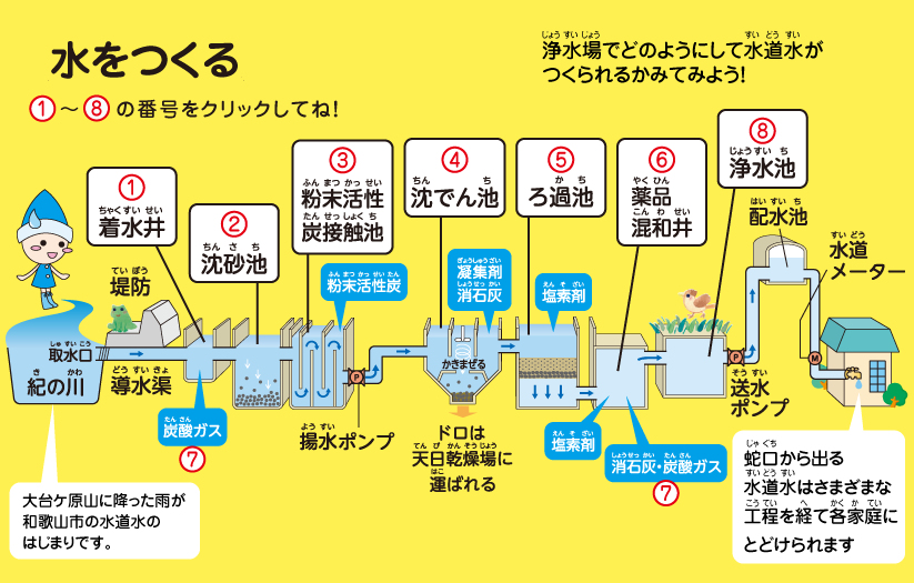
図10 浄水場のしくみの事例 Fig.10 Example of the structure of a water purification plant.
引用資料 Reference material:和歌山市 Wakayama city
(2)家庭排水-小型浄化槽
今日の合併浄化槽は、有機物の除去のみでなく、窒素・リンを除去する高機能を有する製品も多数利用されている。ここでは窒素型小型浄化槽を事例として取り上げる。
浄化槽の構造は、流入水 → 1) 固形物の沈降分離と浄化(嫌気性、2槽)→ 2)曝気槽 → 3) 沈殿槽→ 4)消毒→ 放流のプロセスから構成されている。さらに、2)曝気槽の硝化液を1)無酸素槽へ返送(窒素除去)、3)沈殿槽の汚泥を3)曝気槽の底面へスロットタイプで移動させ、この汚泥をエアリフトで 1)嫌気槽へ返送して貯留/消化する機能を有している。
ここで、1)嫌気槽および2)曝気槽にはそれぞれ異なる担体を付設して、各槽の効率向上を行っている。嫌気槽では固定床、曝気槽では固定床または流動床のいずれかが採用されている。
家庭排水の浄化槽は、コンパクトであるが、酸素供給、汚水・汚泥の移動、ろ床の洗浄・再生などの各機能をエアポンプで行うなど、安定可動性と維持管理上の様々な工夫がなされている。多機能であるが、維持管理(保守点検・清掃・汚泥抜取り)が数ヶ月・年単位でも、公共下水処理場と同等な水質浄化が行えるシステムとなっている。詳しくは、他のページを参照のこと。
編者が特に強調したいことは、自治体と民間が一体となった浄化槽の普及と管理の社会システムが整備され、適正な保守・点検・清掃・汚泥抜取が適正に実施されており、環境問題の解決のみでなく、地域の雇用にも貢献していることである。
(2) Small septic tank for household wastewater
In today’s septic tank “Jokaso” certified in Japan, not only removal of organic substances, but also many products having high function of removing nitrogen and phosphorus are used. Here, a small size of nitrogen removal type septic tank is taken as an example.
The structure of the septic tank consists of processes: inflow water → 1) settling of solids and their digestion (anaerobic, two tanks) → 2) aeration → 3) sludge settling → 4) disinfection → release.
In addition, the nitrification solution in the aeration tank 2) is returned to the anoxic tank 1) (nitrogen removal), sludge in the settling tank 3) is moved to the bottom of the aeration tank 2) through a slot type bottom of the tank 3), and this sludge is returned to the anaerobic tank 1) for storing and digesting it. These functions are dirived by one air pump.
Here, different carriers are attached to anaerobic tank 1) and aeration tank 2) to improve the efficiency of each tank. The anaerobic tank uses a fixed bed, and the aeration tank uses either a fixed bed or a fluidized bed.
Although the domestic wastewater septic tank is compact, it has various contrivances in terms of stable performance and maintenance with functions such as oxygen supply, movement of wastewater and sludge, cleaning and regeneration of the filter bed with an air pump. It has multiple functions, the system has the same water purification performance as a public sewage treatment plant even if maintenance (inspection, cleaning, and sludge removal) is performed for several months or an year. See the page for detail.
What the editor especially wants to emphasize is that a social system for the dissemination and management of septic tanks in which the local government and the private sector are united has been established, and proper maintenance, inspection, cleaning and sludge removal are being carried out properly, rusuling in that the environmental problems is solved and that it contributes to local employment.
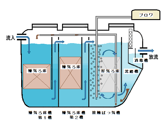
図11 窒素除去型浄化槽 Fig.11 Nitrogen removal type Jokaso (Certified septic tank in Japan).
1) 嫌気ろ床槽 anaerobic tank with fixed filter bed, 2) 好気ろ床槽 aeration tank with fixed filter bed, 3) 沈殿槽 sludge selting tank, and 4) 消毒槽 disinfection tank.
引用資料 Material cited: 小諸市 Komoro city
(3)流動担体型活性汚泥法
活性汚泥法を用いた汚水処理施設での問題点は、1) 計画水量以上の下水の流入、2) 汚泥膨化(バルキング)、3) 窒素・リンの除去、4) 発生汚泥量の削減などがある。これらの解決策の一つとして、曝気タンクへの流動担体法がある。この方法の利点は、曝気槽に担体流出を阻止するスクリーンを付設するだけで上記課題を解決できることにある。
この流動担体型活性汚泥法の特徴は、1)処理効率の向上と設備のコンパクト化、2)運転管理の簡素化、3)発生汚泥の減量化が可能となる。担体の充填率は、曝気槽の有効容積に対して10~20%程度である。流動による担体の量の減少は、定期的に補充を行う。比重が水に近く、曝気攪拌などで、水中に浮遊し、微生物を出来るだけ多く保持できればよいので、様々な材質・形状・性能を有する担体が開発・実用化されている。上記の浄化槽での曝気槽への導入も同じ原理である。2つの流動担体の事例を下記の写真に示す。
(3) Fluidized carrier type activated sludge process
The problems in the wastewater treatment facility using the activated sludge method are 1) inflow of wastewater more than the planned amount of water, 2) sludge expansion (bulking), 3) removal of nitrogen and phosphorus, 4) reduction of the amount of generated sludge. As one of these solutions, there is a fluidized carrier method for an aeration tank. The advantage of this method is that the above-mentioned problems can be solved only by attaching a screen for preventing carrier outflow to the aeration tank.
The features of this fluidized carrier type activated sludge method are 1) improvement of treatment efficiency and downsizing of equipment, 2) simplification of operation management, and 3) reduction of generated sludge. The carrier filling rate is about 10 to 20% of the effective volume of the aeration tank. To reduce the amount of carrier due to flow, replenishment is performed regularly. Since the specific gravity is close to that of water and it can suspend in water by aeration and stirring to retain as many microorganisms as possible, carriers having various materials, shapes and performances have been developed and put into practical use. The same principle applies to the aeration tank in the above septic tank and the detail is described in the section 2.(6) and shouwn in Fig.6. The following photos show two examples of fluidized carriers.
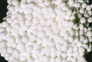
写真1 流動担体事例1)Fluidized carrier exampl 1) クラゲール Kuragel
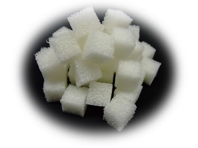
写真2 流動担体事例2)Fluidized carrier exampl 2) アクアキューブ Aquacube
(4)工業排水-難分解性有機物
2,3,4,4-tetrahydroxybenzophenone(THBP)は半導体製造に用いられるフォトレジストの原料である。THBP製造工程排液の主な汚濁物質はTHBPで他に少量の原料および副生成物を含み、これらの汚濁物質は芳香族系の化合物で、極めて生物難分解性である。
本排液処理の基本プロセスは、海水を添加しフェライトを陽極とする電解(図12)により活性電解塩素を発生させ、THBPおよびその副生成物を生物分解性物質へ変換・改質したのち、生物膜法の一つである浸漬ろ床(生物ろ過、図13および写真3)法により除去する方法である。この事例は、特殊な排水を処理できる微生物を育成・保持できる生物膜法を利用したものである。増殖率が遅く馴致期間も半年以上を要するが、生成する汚泥も極めて少ないことが特徴である。活性汚泥法へのスケールアップの基礎実験としての事例である。詳しくは、文献を参照のこと。
(4) Industrial wastewater-hard-degradable organic matter
2,3,4,4-Tetrahydroxybenzophenone (THBP) is a raw material for photoresists used in semiconductor manufacturing. The main pollutant in the effluent of the THBP manufacturing process is THBP, which also contains a small amount of raw materials and by-products. These pollutants are aromatic compounds and extremely bio-undegradable.
The basic process of this effluent treatment is to generate active chlorine by electrolysis (Fig.12) with seawater added and ferrite as the anode, and to convert/reform THBP and its by-products into biodegradable substances, and then use the biofilm method. It is a method of removing by one of the immersion filtration (biological filtration, Fig.13 and Photo 3) methods. This case uses a biofilm method that can grow and retain microorganisms that can treat special wastewater. The growth rate is slow and the acclimatization period requires more than half a year, but the feature is that very little sludge is generated. This is a case as a basic test experiment for scale-up to to activated sludge method. See the literature for details.
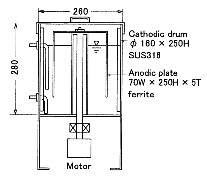
図12 電解実験装置 Fig.12 Electrolysis experimental device.
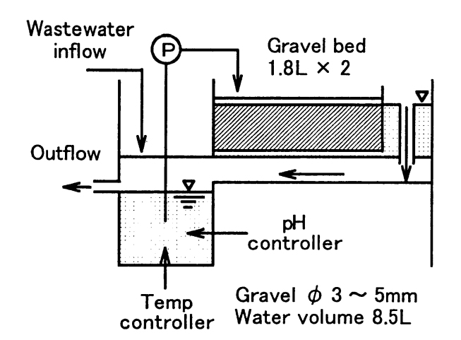
図13 浸漬ろ床実験装置 Fig.13 Immersion filter bed test equipment.
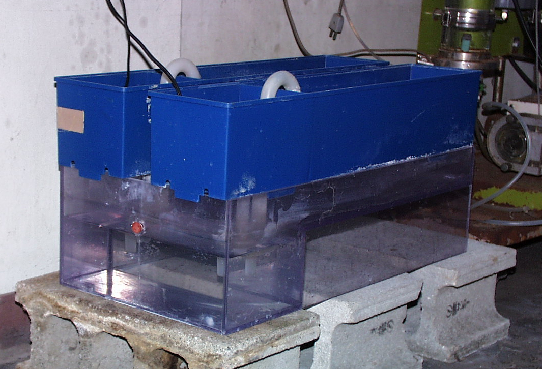
写真3 浸漬ろ床実験装置の全景 Photo 3 View of the immersion filter bed test equipment.
(5)ゼロエミッション型水産養殖-生物ろ過と植生
養殖の自家汚染を防止、生産性の向上と環境破壊の防止を目的として、水耕栽培を併用したゼロエミッション型水産養殖のモデル(図14)である。
このモデルは、飼料 → 魚類 → 残存飼料・排泄物 → 微生物(生物膜)→ 無機塩類 → 水耕栽培(栄養塩類除去)の生態系循環経路より構成される。実験装置の概略を図15および写真4に示す。水耕栽培の生産物は天日乾燥の後、野菜畑の有機栽培に利用する。生物膜法の担体として、吊り下げ紐状を利用している。詳しくは文献を参照のこと。
(5) Zero-emission aquaculture-biological filtration and vegetation
It is a model of zero-emission aquaculture (Fig.14) that uses hydroponic cultivation in order to prevent self-pollution of aquaculture, improve productivity and prevent environmental damage.
This model consists of ecological circulation pathways: feed → fish → residual feed/excretion → microorganisms (biofilter) → inorganic salts → hydroponics (nutrition removal). An outline of the experimental setup is shown in Fig.15 and Photo 4. The hydroponic products are used for organic cultivation of vegetable fields after being dried under the sun. A hanging string is used as a carrier for the biofilm method. See the literature for details.
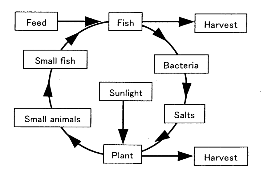
図14 ゼロエミッション型水産養殖のモデル
Fig.14 Zero-emission aquaculture model.
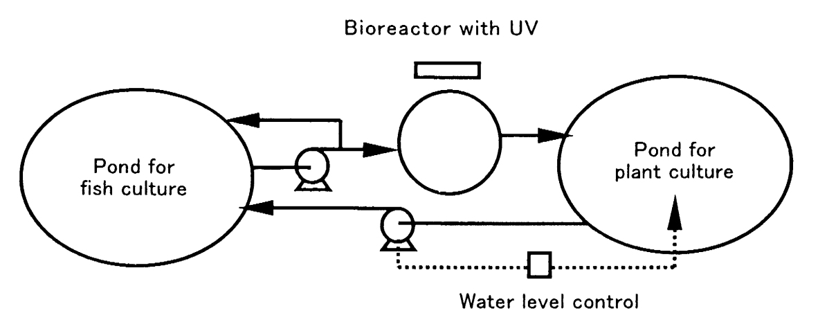
図15 ゼロエミッション型水産養殖の実験装置の概要図
Fig.15 Schematic diagram of zero-emission aquaculture experimental device.
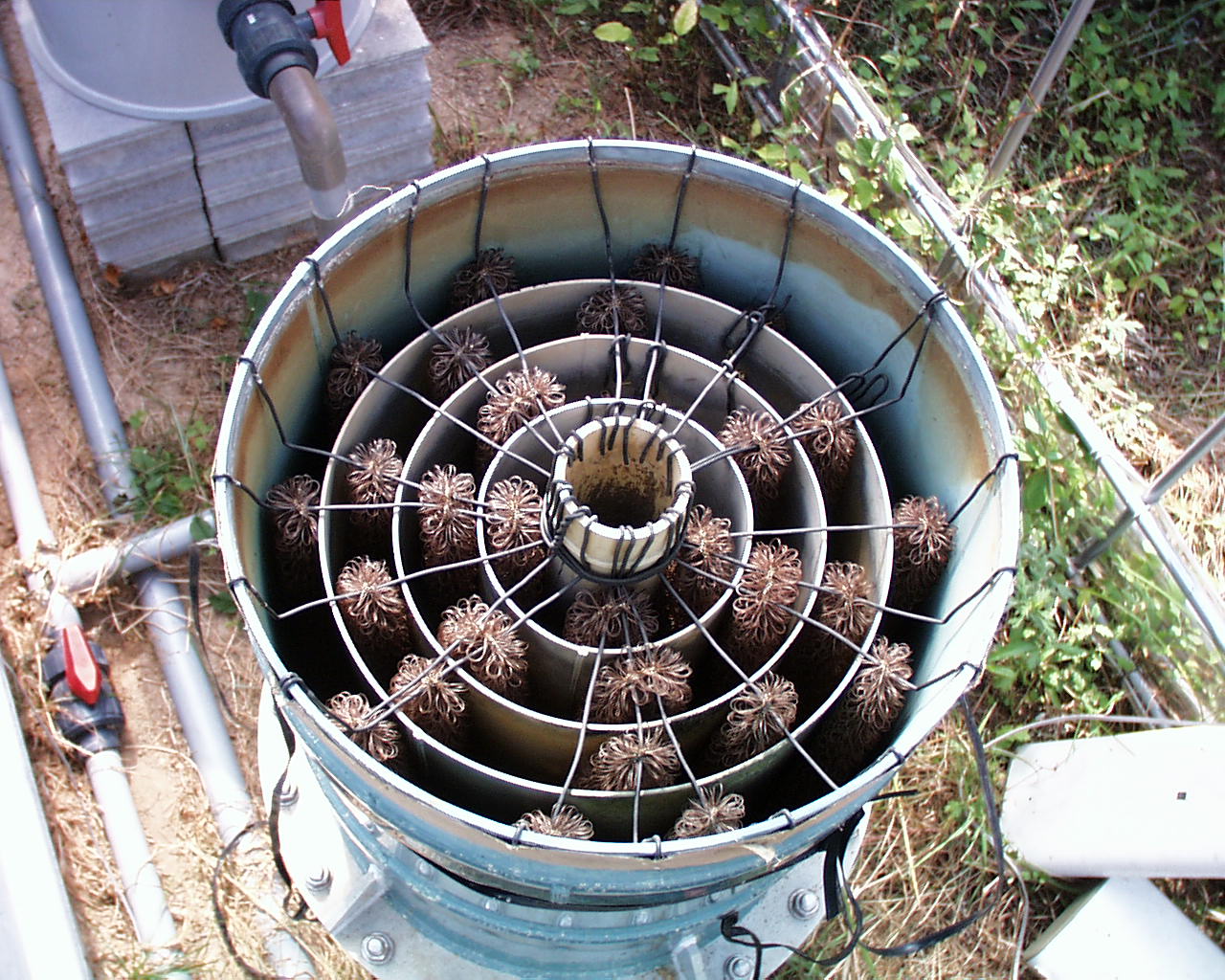
写真4 浸漬ろ床による浄化実験装置
Photo 4 A experimental bioreactor using immersion biofilter.
(5)河川浄化―瀬と淵の造成
川が本来もっている自浄作用を発揮できる「瀬」と「淵」を再現した河川の浄化事例である。建設省が進める様々な河川浄化プロジェクトの一つの事例である。
流れがゆっくりした「淵」では固形物質を沈殿・接触する場を持たせ、水の流れの速い「瀬」では接触酸化に必要な酸素供給と砂礫間を通る際のろ過機能と表面に付着した生物膜により、汚濁物質を除去する。
この方法の特徴は、河川の浄化作用のみでなく、生息する原生・微少動物の種類も多様で、さらに「淵」と「瀬」で棲み分けする大小様々な大小様々な魚種の生息環境を提供することに特徴がある。
(5) River purification-building of rivers and pools
It is an example of river purification that reproduces the “shoal” and “abyss” that can exert the self-cleaning action that the river originally has. This is an example of various river purification projects carried out by MLIT.
In the “abyss” where the flow is slow, there is a place to settle and contact the solid matter, and in the “shoal” where the water flow is fast, the oxygen supply necessary for catalytic oxidation. The water is purified when passing through and/or between the sand and gravel which surfaces are covered with biofilm.
This method is characterized not only by the purifying action of rivers, but also by the providing place for a variety of protozoa and tiny animals that inhabit and for the habitat of various small and large fish to separate living places between “shoal” and “abyss”.
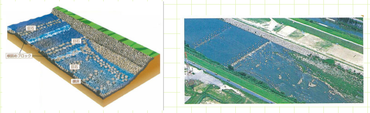
写真16 瀬と淵の造成による河川浄化の事例
Photo 16 A case of river purification by creating a river and a pool
引用資料 Mterial cited: 国土交通省 MLIT (Ministry of Land, Infrastructure, Transport and Tourism)
References
Nikkan Kyoiku Center (Japan Education Center of Environmental Sanitation), 2017: Maintenance of Jokaso (first volume), p.175
Other references, illustrations, photographs, etc. cited are shown in the text.
掲載:2017年10月10日
更新:2020年7月30日(英語版追加)
Posted: October 10, 2017
Update: August 3, 2020 (English version added)
