Activated sludge process – indoor continuous experiment
村上定瞭(水浄化フォーラム), Sadaaki Murakami (Water & Solutions Forum)
1.はじめに
2.実験方法
3.運転管理と操作条件
4.運転管理上の留意事項
活性汚泥法の総目次
Ⅰ. 活性汚泥法とは
Ⅱ. 基本設計・操作因子
Ⅲ. 回分法
Ⅳ. 連続法(本ページ)
Ⅴ. 活性汚泥の悪化と対策
1. Introduction
2. Experimental
3. Operation management and operating conditions
4. Operation management considerations
Total table of activated sludge process
I. What is the activated sludge process?
Ⅱ. Basic design and operation factors
Ⅲ. Batch method
Ⅳ. Continuous method (this page)
Ⅴ. Deterioration of activated sludge and countermeasures
1.はじめに
生活・産業に伴う排水中有機物の浄化には微生物を活用する方法が効果的である。比較的有機物の濃度が低い排水には、活性汚泥法が多用される(総目次のⅠを参照)。
これらの浄化施設は、毎日の排水を処理するため、年間を通した安定稼働が求められる。しかし、活性汚泥プロセスを適切に稼働するには、基本的な知識と経験が求められる。プロセスの管理に求められる各操作因子を理解し、実際に装置を運転して、処理施設の設計・管理に関する技術を習得するための実験手法を紹介する。
ここでは、連続的に排水を処理する方法について解説するが、「基本用語」と「運転条件」に関しては、他ページ(総目次のⅠとⅡ)を参照されたい。
1. Introduction
The method of utilizing microorganisms is effective for the purification of organic matter in wastewater associated with daily life and industry. The activated sludge method is often used for wastewater with a relatively low concentration of organic matter (see Page I in Total table).
These purification facilities process wastewater every day, so stable operation throughout the year is required. However, basic knowledge and experience are required to properly operate the activated sludge process. We will introduce experimental methods to understand each operation factor required for process management, to actually operate the equipment, and to acquire technology related to design and management of processing facilities.
Here, we will explain the method of treating wastewater continuously, but refer to other pages (I and II in the Total table) for “basic terms” and “operating conditions”.
2.実験方法
(1)実験装置
有効容積10Lの曝気槽を用いた活性汚泥装置の事例として、図1にその概略を示す。本装置の各部の詳細を次に示す。適宜、工夫して実験装置を構成するとよい。
1) 原水貯留槽(40~50L):ポリバケツ、定量送液ポンプ、チューブ(内径1mm)
2) 曝気槽(有効容積10L):内径233mm、高さ350mm、水深233mm、厚さ3mmのPVC板で加工)
a) 攪拌器具:マッグネチックスターラー、回転子、曝気槽の底面摩耗防止用ガラス板(直径220mm、暑さ2mm)(曝気を主および補助の2台で運転する場合には、後述するように、攪拌器具は不要となる。)
b) 曝気器具:送気ポンプ、チューブ(内径4mm)、散気球(鑑賞魚水槽用エアディフィーザー)
c) 中和器具:貯留容器(5L)、送液ポンプ、チューブ(内径1mm)
d) 計測制御器:溶存酸素(DO)(隔膜電極)、pH(ガラス-比較一体型電極)
3) 沈殿槽(円錐型、有効容積5L):内径280mm、高さ420mm、有効水深350mm
a) 汚泥掻落器:低速回転モーター、掻落棒
b) 汚泥返送器具:定量送液ポンプ、チューブ(内径1mm)
2. Experimental
(1) Experimental device
Fig.1 shows an outline of an activated sludge device using an aeration tank with an effective volume of 10L. Details of each part of this device are shown below. It is advisable to devise the experiment device appropriately.
1) Raw water storage tank (40 to 50L): Poly bucket, constant-rate volume pump and tube (inner diameter 1mm).
2) Aeration tank (effective volume 10L): Cylindrical and made of PVC plate with inner diameter 233mm, height 350mm, water depth 233mm, thickness 3mm.
a) Stirrer: Magnetic stirrer, rotor and a glass plate to prevent bottom wear of aeration tank (diameter 220 mm, heat 2 mm). When operating aeration with two main and auxiliary units, the stirrer is unnecessary as will be described later.
b) Aeration equipment: Air supply pump, tube (4mm inside diameter) and diffuser (air diffuser for viewing fish tank).
c) Neutralizing device: Storage container (5L), liquid feed pump and tube (inner diameter 1mm).
d) Measurement controllers: Dissolved oxygen (DO) (diaphragm electrode) and pH (Glass-comparative integrated electrode).
3) Settling tank (conical type, effective volume 5L): Inner diameter 280mm, height 420mm, effective water depth 350mm.
a) Sludge scraper: Low speed rotation motor, scraping rod.
b) Sludge return device: Constant-rate liquid feed pump, tube (inner diameter 1mm).
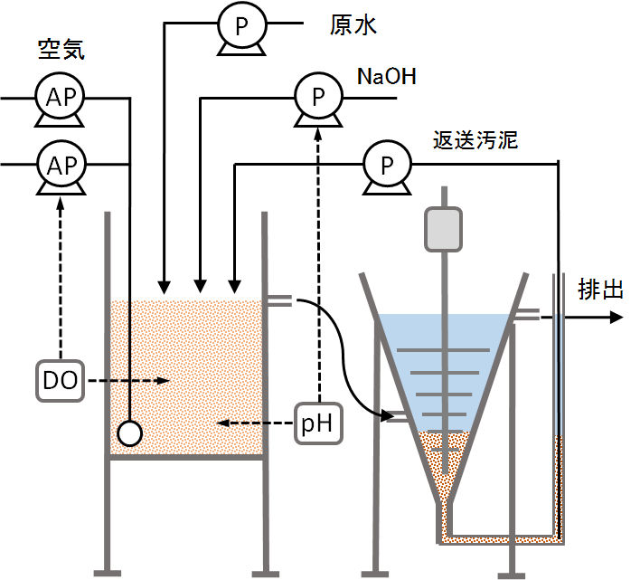
図1 活性汚泥の実験装置(有効容積:曝気槽10L、沈殿槽5L)
Figure 1 Activated sludge experimental equipment (effective volume: aeration tank 10L, sedimentation tank 5L).
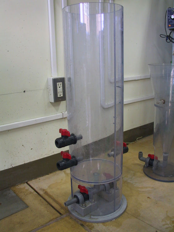
(A1) 曝気槽
Aeration tank
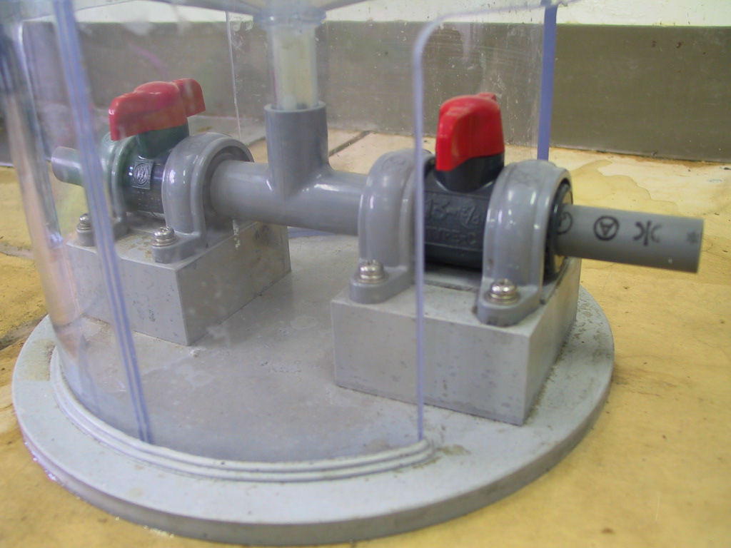
(A2) 曝気槽・底部
Areation tank bottom
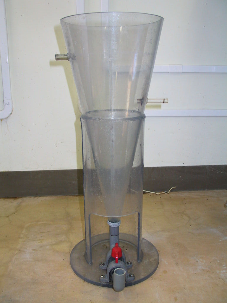
(B1) 沈殿槽
Settling tank
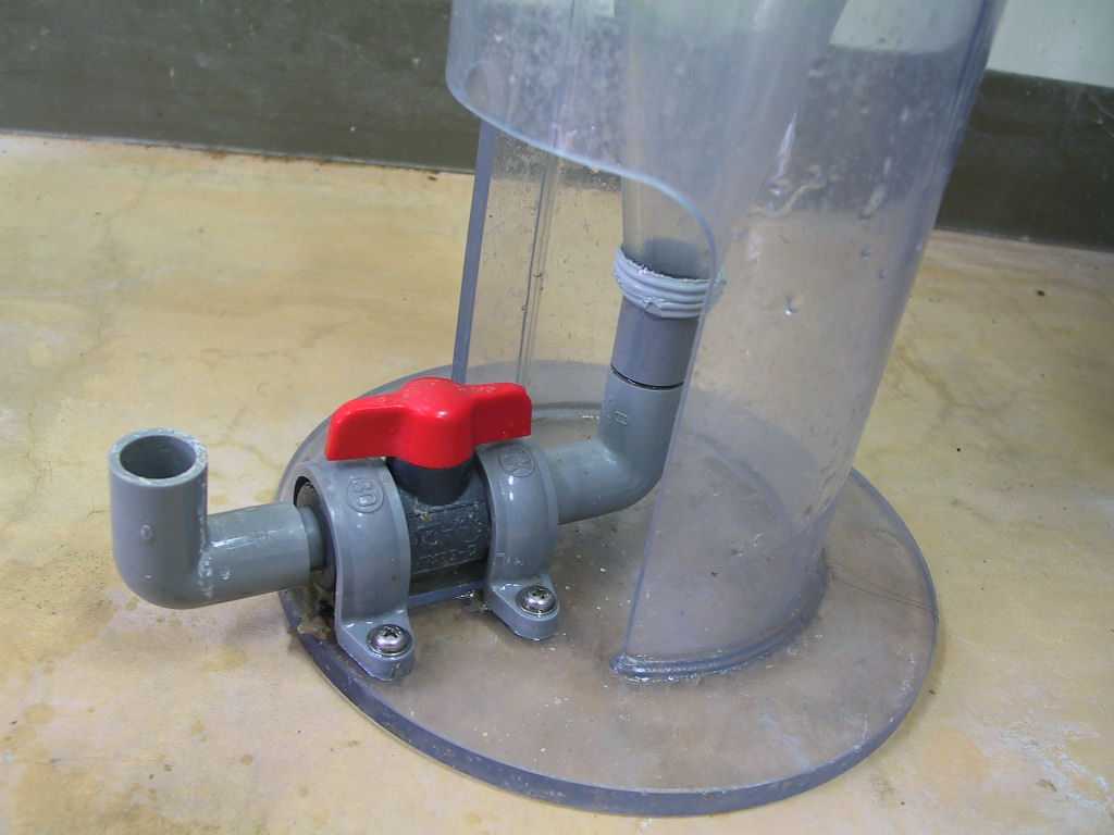
(B2) 沈殿槽・底部
Settling tank bottom
Photo 1 Each part of activated sludge equipment.
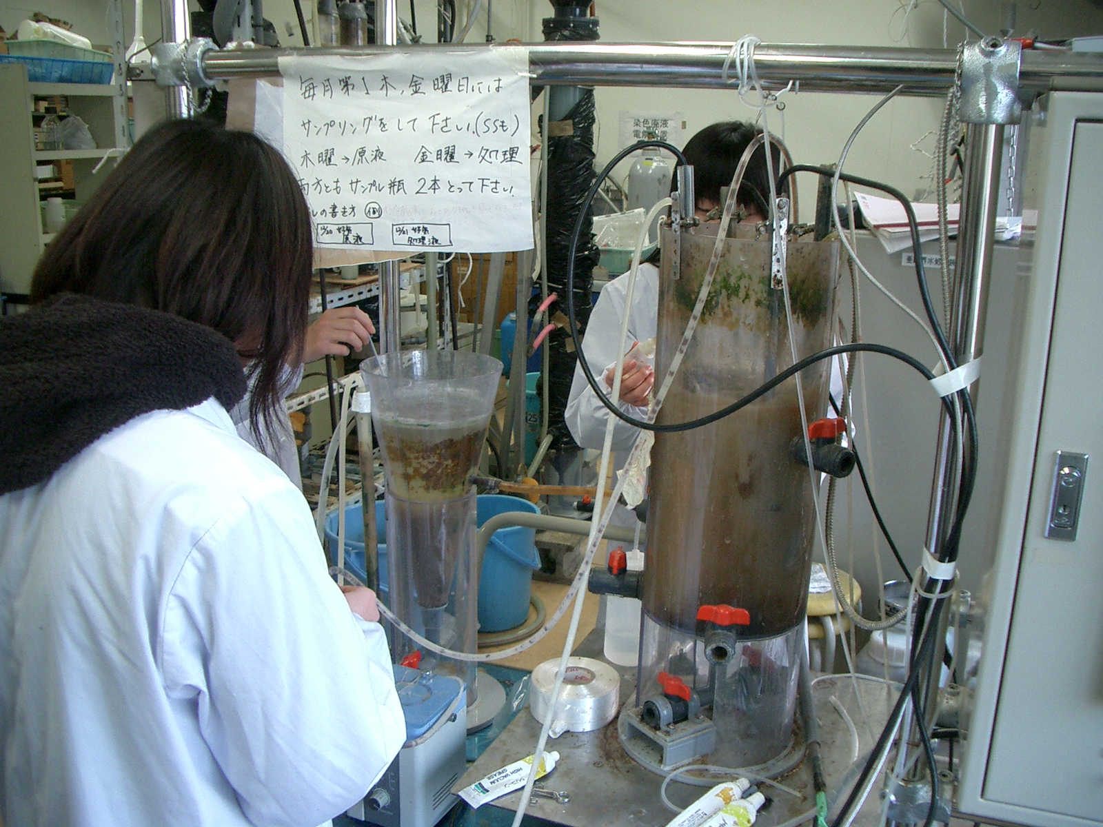
Photo 2 State of activated activated sludge method experiment.
(2)供試排水
実験に用いる排水は、生物分解性の汚濁物質を含むものであれば特に限定しない。
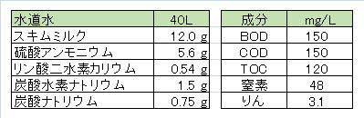
本実験では、都市下水の一般的なBOD濃度である150mg/Lの排水を使用した。表1に模擬下水の組成の一事例として示す。
(2) Test wastewater
The wastewater used in the experiment is not particularly limited as long as it contains biodegradable pollutants.
In this experiment, 150 mg/L of wastewater, which is a general BOD concentration of municipal wastewater, was used. Table 1 shows an example of the composition of simulated sewage.
Table 1 Composition of simulated wastewater and pollutant components.
(3)計測制御
活性汚泥法を適正に管理するための主な操作因子として、溶存酸素(DO)とpHがある。
1) 溶存酸素
連続型活性汚泥プロセスでは、DOを1~3mg/LとなるようにDOを計測して、曝気量の制御をする。ベンチスケールの曝気槽をエアポンプ1台で、曝気をon-off制御すると散気装置(本実験ではポーラス散気球を使用)の目詰まりが生じる。そこで、主ポンプ(連続稼働)と補助ポンプ(on-off制御)の2台を利用するとよい。主ポンプの送気量を負荷量に応じて僅かに不足する程度に調節し、この不足分を補助ポンプで補う程度に調節する。DO計測制御器を補助ポンプに接続して、曝気槽のDOを所定の値に保つ。主ポンプによる曝気は撹拌機能も有する。
溶存酸素計として隔膜電極法(ガルバニックセル法とポーラログラフ法の2つの方式がある。性能・特徴・使用法は同じ。)を採用した計測制御器を使用する。隔膜・電解液の交換、電極の研磨など定期的なメンテナンスや校正作業が必要である。H2S、SO2、ハロゲンガスなどを含む排水では、DO測定の妨害となるので注意する。
2) pH
通常の活性汚泥法では、有機物の酸化によりpHが低下する。中和剤をpH計測制御器に接続した送液ポンプで注入する。ベンチスケール実験では中和剤として、1N-水酸化ナトリウム液を用いるとよい。排水によっては、pHが上昇するものもある。この場合には、1N-硫酸液を添加するとよい。
pH測定では、ガラス電極と比較電極の間に生じた起電力(電位差)を計測する。DO計では電流を、pH計では電圧をそれぞれ測定する。問題は、ガラス電極の抵抗が極めて大きい(300~500MΩ)ので、応答速度が遅い。また、ガラス膜が薄く、破損しやすいことである。破損防止のキャップを付ける(オプションでない場合には、半田ごてなどで穴を開けた円筒型プラスチックを電極先端を覆うように取り付ける。)。
電極の保守には、1) 電極の洗浄、2) 標準液校正、3) 電極内部液の補充などがある。
曝気槽内混合液内では、ガラス電極や比較電極の液絡部に、懸濁物・粘性物質・微生物(清水で洗い落とす)、油性物質(中性洗剤溶液に浸す)や金属塩(1~2%の塩酸溶液に浸す)などの汚れが付着しやすいので、電極の洗浄を定期的に行う。
標準液校正は、測定条件により大きく異なるので、運転当初は1週間ごとに校正し、データを記録して、校正間隔を決めるとよい。
電極ホルダー中の内部液(3mol塩化カリウム溶液)が十分入っているか確認する。不足している場合には、補充する。
(3) Measurement and control
Dissolved oxygen (DO) and pH are the main operating factors for proper management of the activated sludge process.
1) Dissolved oxygen
In the continuous activated sludge process, DO is measured to be 1 to 2 mg/L and the aeration amount is controlled. If the bench scale aeration tank is controlled by one air pump and the aeration is turned on and off, the air diffuser (a porous air diffusing bulb is used in this experiment) becomes clogged. Therefore, it is advisable to use two main pumps (continuous operation) and auxiliary pumps (on-off control). The amount of air sent from the main pump is adjusted so that it is slightly insufficient according to the load, and the amount of this shortage is adjusted by an auxiliary pump. Connect the DO measurement controller to the auxiliary pump to keep the DO in the aeration tank at the specified value. Aeration by the main pump also has a stirring function.
As a dissolved oxygen meter, a measurement controller that adopts the diaphragm electrode method (the galvanic cell method and the polarographic method are used. The performance, characteristics, and usage are the same) is used. Periodic maintenance such as diaphragm/electrolyte exchange and electrode polishing and calibration work are required. Be aware that wastewater containing H2S, SO2, halogen gas, etc. will interfere with DO measurement.
2) pH
In the usual activated sludge method, the pH decreases due to the oxidation of organic matter. Inject the neutralizer with the liquid feed pump connected to the pH measurement controller. In a bench scale experiment, 1N-sodium hydroxide solution should be used as a neutralizing agent. Depending on the effluent, the pH may increase in some cases. In this case, 1N-sulfuric acid solution may be added.
In pH measurement, the electromotive force (potential difference) generated between the glass electrode and the reference electrode is measured. The DO meter measures current and the pH meter measures voltage. The problem is that the resistance of the glass electrode is extremely high (300 to 500 MΩ), so the response speed is slow. In addition, the glass film is thin and easily damaged. Attach a cap to prevent damage (if it is not an option, attach a cylindrical plastic with holes such as a soldering iron to cover the tip of the electrode).
Electrode maintenance includes 1) electrode cleaning, 2) standard solution calibration, and 3) electrode internal solution replenishment.
In the mixed liquid in the aeration tank, the liquid junction of the glass electrode or reference electrode are likely adhered by suspended solids, viscous substances, microorganisms (wash off with fresh water), oily substances (immerse in neutral detergent solution), metal salts (dip in 1 to 2% hydrochloric acid solution), so wash the electrodes regularly.
Since the standard solution calibration varies greatly depending on the measurement conditions, it is recommended to calibrate every week at the beginning of operation, record the data, and determine the calibration interval.
Check if the internal solution (3mol potassium chloride solution) in the electrode holder is sufficient. If there is a shortage, replenish it.
3. Operation management and operating conditions
Since it was explained in detail in the batch experiment (III of the total table of contents), the operating conditions are briefly explained here.
(1)負荷量の決定
この実験では曝気槽の容積(10L)と流入原水のBOD濃度が決まっているので、原水の適正流入量を決定する。
ここでは汚泥濃度Sa = 2,000mg/L(仮定)とする。標準活性汚泥法の適正負荷Γsは0.2~0.4kg-BOD/kgSSであるので、Γsを0.3とすると、表2に示す原水流入量 Qi = 40L/dとなる。また、表3に示すように、曝気槽内に微生物(汚泥)を適正に保持できる負荷量にある。
(1) Determination of load amount
In this experiment, the volume 10L of the aeration tank and the BOD concentration of the raw water inflow were determined, so the appropriate inflow of raw water is determined.
Here, the sludge concentration is asumed as Sa = 2,000 mg/L. Since the appropriate load Γs of the standard activated sludge method is 0.2 to 0.4 kg-BOD/kgSS, if Γs is 0.3, the raw water inflow rate is that Qi = 40L/d shown in Table 2. Further, as shown in Table 3, the load is such that microorganisms (sludge) can be properly retained in the aeration tank.
(2)活性汚泥濃度の決定
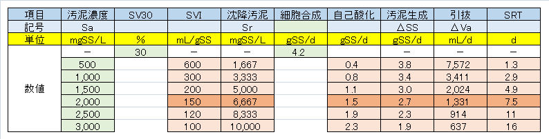
曝気槽内の適正な汚泥濃度を決定する。表2に示すようにSV30 = 30%としたときの、各活性汚泥濃度に対するSVIを推定すると、SVIを150mL/gSS以下に保つ最低濃度は2,000mg-SS/Lとなる。
上記の理由から、本実験では汚泥濃度Sa = 2,000mg-SS/L、流入原水量Qi = 40L/dが適正な操作条件となろう。分離槽から曝気委槽への返送比は43%以上とする。
この操作条件では、余剰汚泥として曝気槽の混合液1.3L/dを引き抜く。実施設では、余剰汚泥の引抜は返送汚泥の一部を引き抜くが、ベンチスケール(数十L程度)では返送汚泥の濃度が変化し、適正な引抜が困難であるので、曝気槽の混合液を引き抜くことに留意する。
(2) Determination of activated sludge concentration
Determine the appropriate sludge concentration in the aeration tank. As shown in Table 2, when SV30 = 30%, the SVI for each activated sludge concentration is estimated, and the minimum concentration that keeps the SVI below 150 mL/gSS is 2,000 mg-SS/L.
Under this operating condition, 1.3L/d of the mixed liquid in the aeration tank is extracted as excess sludge. At the real facility, a part of the returned sludge will be extracted as the excess sludge. At bench scale (several tens of liters), the concentration of the returned sludge changes and proper extraction is difficult, so be careful to extract the mixed liquid in the aeration tank.
Table 2 Operation management items (1) – BOD load and operating conditions.
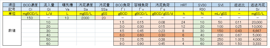
Table 3 Operation management items (2) – Sludge generation and operating conditions.
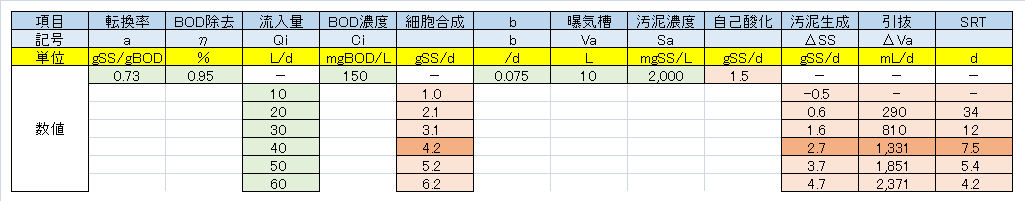
Table 4 Operation management items (3) – Sludge concentration and operating conditions.
4.運転管理の留意事項
強熱残留物と汚泥の沈降性
本実験では、下水汚泥の返送汚泥を活性汚泥として植種した。一般に、下水汚泥には強熱残留物(IR)が汚泥中15~25%程度含まれている。このIRの成分は、無機塩類、金属酸化物、粘度鉱物などの下水中にふくまれる懸濁状微粒子である。下水返送汚泥中のIR量と組成は、天候条件により大きく異なる。
図2に下水汚泥を植種し、スキムミルクを主成分とする模擬排水を投入した活性汚泥プロセス(原水:300mg-BOD/L、HRT = 24h、MLSS = 1,800mg-SS/L、Sr(返送汚泥)=7,200mg-SS/L、SRT = 20d)におけるVSS/SSの経日変化を示す。VSS/SSは植種当初70%であったものが20日で90%となり、以後、一定の値で推移している。これは当初含まれていたIR成分が余剰汚泥の引き抜きに伴って減少し、STR 20日以後にはほぼ消失しているものと思われる。一方で、余剰汚泥の濃縮液(1時間程度静置後)は当初10,000mg-SS/Lであったものが、7,000mg-SS/Lにまで減少した。このことは、強熱残留物が汚泥の良好な沈降性を担っていることを示している。
模擬排水には金属酸化物や粘度鉱物の微粒子が存在しないので、沈降性の改善のため、カオリナイトなどの粘土成分を添加すると現実の下水性状に近くなり、沈降性が改善される。添加量としては、Sa[mg-SS/L]×Va[L]×0.1/SRT[d]、を目安とする。Sa = 1,500mg-SS/L、Va = 10L、SRT = 8dであれば、1.9g-kaolin/d程度となる。
4. Operation management considerations
Ignition residue and sludge settlingability
In this experiment, returned sludge from sewage sludge was planted as activated sludge. In general, sewage sludge contains 15 to 25% of ignition residue (IR) in the sludge. The components of this IR are suspended fine particles contained in sewage such as inorganic salts, metal oxides and clay minerals. The amount and composition of IR in sewage return sludge vary greatly depending on weather conditions.
Fig.2 shows changes in VSS/SS over time for the activated sludge process in which sewage sludge is planted and simulated wastewater containing skim milk as main component is added (raw water: 300mg-BOD/L, HRT = 24h, MLSS = 1,800mg-SS/L, Sr(returned sludge) = 7,200mg-SS/L, SRT = 20d). VSS/SS was 70% at the beginning of planting, but became 90% in 20 days, and has remained constant since then. This seems to be because the IR component initially contained decreased with the removal of excess sludge, and almost disappeared after 20 days of STR. On the other hand, the concentration of excess sludge (after standing for about 1 hour) was initially 10,000 mg-SS/L, but decreased to 7,000 mg-SS/L. This indicates that the ignition residue is responsible for good sludge settling properties.
Since there are no metal oxides or fine particles of clay minerals in the simulated wastewater, adding clay components such as kaolinite to improve the sedimentability by making it close to the actual sewage sludge. As the amount of addition, Sa[mg-SS/L] × Va[L] × 0.1/SRT[d] is a standard. If Sa = 1,500mg-SS/L, Va = 10L, SRT = 8d, it will be about 1.9g-kaolin/d to be added.
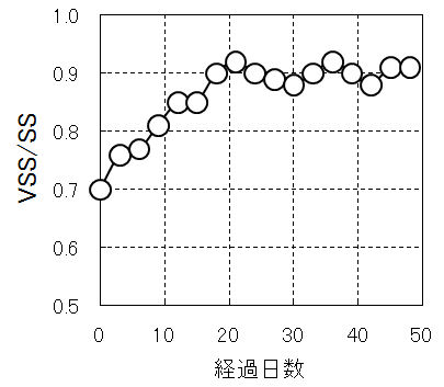
図2 下水処理場返送汚泥を植種した活性汚泥実験におけるVSS/SSの経日変化
Fig.2 Daily change of VSS/SS in the activated sludge experiment in which the sludge returned from the sewage treatment plant was planted.
原水(Raw wastewater):300mg-BOD/L、HRT = 24h、MLSS = 1,800mg-SS、Sr = 7,200mg-SS/L、SRT = 20d
公開:2017年05月10日
更新:2020年07年22日(英語版追加)
Published: May 10, 2017
Updated: July 22, 2020 (English version added)
