Basic design and operating factors of activated sludge process
村上定瞭(水浄化フォーラム), Sadaaki Murakami (Water & Solutions Forum)
1.活性汚泥法の基本設計・運転管理の項目
1. Items for basic design and operation management of activated sludge process
2. Example of basic design and operation management of activated sludge process
活性汚泥法の総目次
Ⅰ.活性汚泥法とは
Ⅱ.基本設計・操作因子(本ページ)
Ⅲ.回分型-室内実験
Ⅳ.連続型-室内実験
Ⅴ.活性汚泥の悪化と対策-室内実験
Ⅵ.高酸素濃度型-余剰汚泥なし
Ⅶ.汚泥減量型
Ⅷ.膜分離型-室内実験
Total table of activated sludge process
Ⅰ. What is the activated sludge process?
Ⅱ. Basic design and operation factors (this page)
Ⅲ. Batch type – indoor experiment
Ⅳ. Continuous type – indoor experiment
Ⅴ. Deterioration of activated sludge and countermeasures
Ⅵ. High oxygen concentration type – no excess sludge
Ⅶ. Sludge reduction type
Ⅷ. Membrane separation type – indoor experimrnt
はじめに
ここでは、活性汚泥法の設計・運転に係る項目について解説する。活性汚泥法の室内実験方法について、回分法・連続法の装置および運転は、別ページ(上記の総目次のⅢ~Ⅳ)に記載してあるので、ここで示す各項目の具体的な理解と実践に活用されたい。
初心者が、活性汚泥(回分・連続を問わず)の実験を行うと、様々な困難に遭遇する。この障害を乗り越えることで、現場で起こる課題に対しても、対応・対策を実施することができるようになる。活性汚泥の実験に係るページ「活性汚泥の性状悪化と対策-屋内実験」(上記の総目次のⅤ)および「活性汚泥・酸素消費速度の測定法と応用事例」についても、参考にされたい。
Introduction
Here, the factors related to the design and operation of the activated sludge process are explained. Regarding the laboratory experiment system of the activated sludge process, the equipment and operation of the batch process and the continuous process are described on a separate page (see Ⅲ and Ⅳ of Total table above). Please use them for concrete understanding and practice of each factor shown here.
A beginner encounters various difficulties when conducting experiments on activated sludge (both batch and continuous). By overcoming this obstacle, it will be possible to implement measures and countermeasures even for problems that occur at the site. Also refer to the page V of Total table above and “Measurement method of activated sludge and oxygen consumption rate and application examples” concerning the experiment of activated sludge process.
1.活性汚泥法の基本設計・運転管理の項目
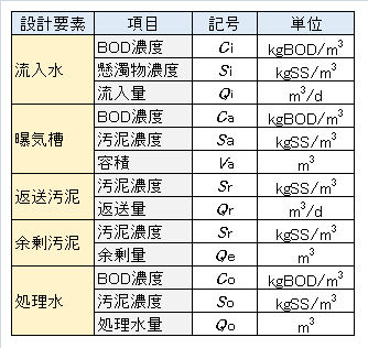
ここでは、活性汚泥プロセスの設計および操作に係る項目について説明する。図1に活性汚泥法の模式図、表1に設計・操作因子項目を示す。なお、濃度の単位[kg/m3] はそのまま[g/L]に置き換えてよい。
1. Factors of basic design and operation management for activated sludge process
Here, the factors related to the design and operation of the activated sludge process will be described. Fig.1 shows a schematic diagram of the activated sludge method, and Table 1 shows the design and operation factor items. The concentration unit [kg/m3] may be directly replaced with [g/L].
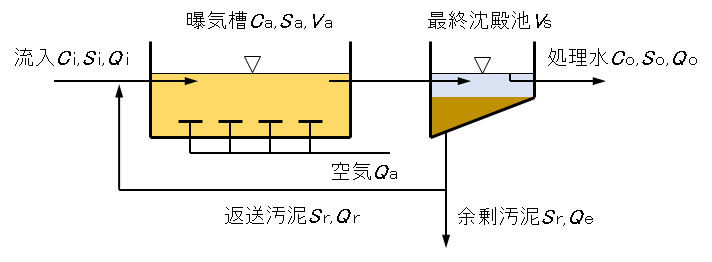
図1 活性汚泥プロセスの設計・操作因子
Fig.1 Design and operation factors of activated sludge process.
Table 1 Design and operating factors of activated sludge process.
SS(Suspended Solid)
SSは水中に懸濁状で存在する非溶解性物質の総称で、その濃度は懸濁液に含まれる汚泥の乾燥重量[mg/L]で表される。活性汚泥法では、SSは水を浄化する微生物を意味し、これを活性汚泥(このページでは汚泥と略称する)という。この汚泥には、微生物の他に、流入水由来及び処理中に生成した不溶性の無機物などが含まれている。
SS (Suspended Solid)
SS is a general factor for non-soluble substances existing in suspension in water, and its concentration is expressed by the dry weight [mg/L] of sludge contained in the suspension. In the activated sludge method, SS means a microorganism that purifies water, which is called activated sludge (abbreviated as sludge on this page). In addition to microorganisms, this sludge contains insoluble inorganic substances derived from influent water and generated during treatment.
ML(Mixed Liguor)
曝気槽内において流入水と汚泥の混合液をいう。
ML (Mixed Liguor)
A mixture of influent and sludge in the aeration tank.
MLSS(Mixed Liquor Suspended Solid)
混合液中の汚泥濃度で、単位容積の混合液中の汚泥の乾燥重量[mg-SS/L]で示される。
MLSS (Mixed Liquor Suspended Solid)
Sludge concentration in the mixed liquor, expressed as dry weight [mg-SS/L] of sludge in the unit volume of mixed liquor.
MLVSS(Mixed Lquor Volatile Solid)
MLSS測定の後、この乾燥汚泥を強熱しその減量からMLVSSの値[mg-VSS/L]を求める。MLVSSは汚泥中の有機物量を意味し、MLSSより実際の微生物量に近い値を示す。通常の下水処理場では、MLSSの75~85%を示すことが多い。
MLVSS (Mixed Lquor Volatile Solid)
After the MLSS measurement, the dried sludge is ignited and the MLVSS value [mg-VSS/L] is calculated from the weight loss. MLVSS means the amount of organic matter in sludge, which is closer to the actual amount of microorganisms than MLSS. Normal sewage treatment plants often show 75-85% of MLSS.
返送比 r
返送比 r は、原水流入量(Q i)に対する返送汚泥量(Q r)の比で示される。r は曝気槽内のSS濃度(S a)の制御に重要な項目である。
Return ratio r
The return ratio r is indicated by the ratio of the amount of returned sludge (Qr) to the amount of raw water inflow (Q i) . r is an important item for controlling the SS concentration (Sa) in the aeration tank.
SV30(Sludge Volume)
曝気槽内の汚泥混合液1L(1,000mL)をメスシリンダーに入れ、30分間静置したときの沈降汚泥が占める容積V30[mL]の元の汚泥混合液容積に対する割合[%]で示す。
SVI も汚泥の沈降性を示す指標であるが、単位が異なるので注意する。SV30の適正値は20~30%であり、SV30の値が大きくなると沈殿池の上澄液量が少なくなり、汚泥の分離効率が低下する。
= V30 [mL]/1,000[mL]×100
・・・ (2)
SV30 (Sludge Volume)
1 L (1,000 mL) of the sludge mixture in the aeration tank is put into a graduated cylinder and SV30 is shown as the ratio [%] of the volume V30 [mL] occupied by the settled sludge when left to stand for 30 minutes to the original sludge mixture volume.
SVI is also an indicator of sludge sedimentation, but be careful because the unit is different. The appropriate value of SV30 is 20 to 30%, and when the value of SV 30 is large, the amount of supernatant in the sedimentation basin is small and sludge separation efficiency is reduced.
SVI(Sludge Volume Index
汚泥容積指数[mL/g]といい、単位重量当たりの沈降汚泥の容積で示される。活性汚泥の沈降性を示す。SVI は、曝気槽内の汚泥混合液1Lをメスシリンダーに入れ、30分間静置したときの沈降汚泥が占める容積V30[mL]を測り、活性汚泥 1gが占める容積[mL]に換算する。
正常な活性汚泥のSVI は 50~150の範囲にあり、200を超えると沈殿池での汚泥界面が水面近くまで上がり、汚泥が処理水中に流出するおそれがある。
= V30 [mL]/Sa [mg/L]×1,000[mL]
= SV30 [-]×10,000/Sa [mg/L]
・・・ (3)
SVI (Sludge Volume Index)
It is called the sludge volume index [mL/g] and is indicated by the volume of settled sludge per unit weight, and shows sedimentation of activated sludge. In SVI, 1 L of the sludge mixed solution in the aeration tank is put into a graduated cylinder and the volume V30 [mL] occupied by the settled sludge when left standing for 30 minutes is measured and converted into the volume [mL] occupied by 1 g of activated sludge.
Normal activated sludge has an SVI in the range of 50 to 150. If it exceeds 200, the sludge interface level in the settling basin may rise close to the water level, and sludge may flow into the treated water.
BOD容積負荷 Γv
曝気槽に流入する有機物(BOD換算)量で、曝気槽の単位容積への1日のBOD流入量Γv [kg-BOD/m3/d]で示される。
= C i×Q i/Va
・・・ (4)
BOD volumetric load Γv
The amount of organic matter (BOD equivalent) that flows into the aeration tank, which is indicated by the daily BOD inflow rate Γv [kg-BOD/m3/d] per unit volume of the aeration tank.
BOD汚泥負荷 Γs
曝気槽容積Vaの決定や運転管理の上で重要な設計・操作因子である。曝気槽に流入するBOD量と活性汚泥量(SSa)の比Γs [kg-BOD/kg-SS/d]で示される。
= C i×Q i/Sa/Va
・・・ (5)
BOD sludge load Γs
It is an important design or operation factor in determining the aeration tank volume Va and in operation management. It is shown by the ratio Γs [kg-BOD/kg-SS/d] of the amount of BOD flowing into the aeration tank and the amount of activated sludge (SSa )
生成汚泥(余剰汚泥)
活性汚泥法では微生物が有機物を摂取して増殖し、汚泥が新たに生成する。この生成量を一日当たりの増加量ΔSS [kg-SS/d]で示す。これは余剰汚泥として、沈殿池から一部の汚泥(Sr×Qe)を引き抜き、残りの汚泥(Sr×Qr)を曝気槽へ返送して、その活性汚泥濃度Saを一定に保つ。
ΔSSは流入水のBOD濃度、曝気時間、汚泥中の微生物量の割合などによって異なるが、一般的な経験式として(6)式で示される。なお、流入水中のS iは考慮していない。(6)式を表1のパラメーターで表すと、(7)式が得られる。
= a×ΔBOD – b×SSa
・・・ (6)
ここで、a [kg-SS/KgBOD]:汚泥変換率、ΔBOD [kg-BOD/d]:除去されたBOD量、b [1/d]、:自己酸化(内生呼吸)の平均速度, SSa [kg-SS]:曝気槽内のSS量である。
Where a [kg-SS/Kg-BOD]: sludge conversion rate, ΔBOD [kg-BOD/d]: amount of BOD removed, b [1/d]: average rate of auto-oxidation (endogenous respiration), SSa [kg-SS]: amount of SS in the aeration tank.
= a×η×C i×Q i – b×Sa×Va
・・・ (7)
ここで、η [%]:BODの除去率である。
Here, η [%]: BOD removal rate.
Produced sludge (excess sludge)
In the activated sludge process, microorganisms ingest organic matter and proliferate, and sludge is newly generated. The production amount per day of increment is shown in ΔSS [kg-SS/d]. This, as excess sludge (Sr×Qe), is pulled out from the settled sludge in the sedimentation tank, and the remaining sludge (Sr×Qr) is returned to the aeration tank, to keep a constant activated sludge concentration (Sa), in the aeration tank.
ΔSS varies depending on the BOD concentration of influent water, the aeration time, the ratio of the amount of microorganisms in sludge, etc., but it is expressed by equation (6) as a general empirical equation. Note that S i in the inflow water is not considered. When the equation (6) is represented by the parameters in Table 1, the equation (7) is obtained.
酸素消費量
酸素はBODの酸化分解および微生物の内生呼吸で消費されので、一般的には経験式(8)で示される。
a‘とb‘は流入水の有機物の種類や活性汚泥プロセスの維持管理条件に依存し、SRTによって大きく左右される。図2に、一般的な家庭排水について、SRTに対する係数a'[kgO2/kgBOD]とb’[kL-O2/kgSS/d]の値の一例を示す。(参照:係数 a’および b’の測定)
Oxygen consumption
Since oxygen is consumed by oxidative decomposition of BOD and microbial endogenous respiration, it is generally represented by empirical formula (8).
a‘and b‘ depend on the type of organic matter in the inflow water and the maintenance conditions of the activated sludge process, and are greatly influenced by SRT . Fig.2 shows an example of the values of coefficients a‘[kg-O2/kg-BOD] and b‘ [kL-O2/kg-SS/d] for SRT for general domestic wastewater. (Reference: Measurement of coefficients a‘ and b‘ )
= a‘×ΔBOD + b‘×SSa
・・・ (8)
ここで、O2[kg-O2/d]は一日当たりの酸素消費量である。
a‘[-]は除去BODの内、微生物(SS)の増殖エネルギー獲得に消費される酸素の割合であり、一般に1よりも小さい。b‘[1/d]は、微生物(SS)の内生呼吸に利用される酸素量の割合である。
Here, O2 [kg-O2/d] is the oxygen consumption amount per day.
a‘[-] is the proportion of oxygen consumed in the growth energy acquisition of microorganisms (SS) in the removed BOD, which is generally smaller than 1. b‘[1/d] is the percentage of oxygen used for endogenous respiration of microorganisms (SS).

図2 消費酸素推定の係数 a’および b’の例
Fig.2 Examples of coefficients a‘ and b‘ for estimating oxygen consumption.
SRT(Sludge Retention Time)
SRTは汚泥滞留時間といわれ、汚泥(SS)が処理系内に滞留している平均日数Ts[d]である。SRTは(9)式で示される。
一般的に、SSsおよびSSpがSSaに比べて相当少なく、SSoが極めて少ないものとすると、SRTは(10)式で示される。
= (SSa + SSs + SSp)/(SSe + SSo)
・・・ (9)
ここで、SSa [kg]:曝気槽内のSS量、SSs [kg]:沈殿池内のSS量、SSp [kg]:返送配管内のSS量、SSe [kg/d]:1日分の余剰汚泥量ΔSS [kg]、SSo [kg]:処理水中の一日分のSS量。
where SSa [kg]: SS amount in the aeration tank, SSs [kg]: SS amount in the sedimentation tank, SSp [kg]: SS amount in return piping, SSe[kg]: Excess sludge amount ΔSS [kg] for one day, SSo [kg]: SS amount in treated water for one day.
≒ SSa/SSe
= Sa×Va/Sr/Qe
・・・ (10)
SRT (Sludge Retention Time)
SRT is called sludge retention time and is the average number of days Ts [d] that sludge (SS) remains in the treatment system. The SRT is expressed by equation (9).
In general, if SSs and SSp are considerably smaller than SSa and SSo is extremely small, then SRT is expressed by equation (10).
HRT(hydraulic Retention Time)
HRTは水理学的滞留時間といい、流入水が処理槽内に滞留している平均的な時間[h]を示す。HRTは施設の設計上、重要な項目である。
曝気槽滞留時間(曝気時間)HTRaおよび沈殿池滞留時間(沈降時間)HTRsは、それぞれ(11)式および(12)式で示される。
= Va/Q i×24
・・・ (11)
= Vs/Q i×24
・・・ (12)
HRT(hydraulic Retention Time)
HRT is called the hydraulic retention time, which indicates the average time [h] that the inflow water stays in the treatment tank. HRT is an important item in facility design.
The aeration tank residence time (aeration time) HTRa and the sedimentation tank residence time (sedimentation time) HTRs are expressed by equations (11) and (12), respectively.
r と汚泥濃度の関係
返送汚泥比(r)と曝気槽汚泥濃度(Sa)および返送汚泥濃度(Sr)との関係は、(13)式で示される。この式は次のようにして導かれる。図1において、流入水中の汚泥濃度Siおよび処理水中の汚泥濃度Soは、曝気内の汚泥濃度Saに比べてとても低いものとし、曝気槽内の活性汚泥の生成(増加)量は余剰汚泥の引き抜きによりSaは一定に保たれているとすると、曝気槽における汚泥の物質収支は(14)式で示される。(14)式と(1)式の関係から(13)式が得られる。
= Q r/Q i
≒ Sa/(Sr – Sa)
・・・ (13)
≒ Sa(Q i + Q r)
・・・ (14)
Relationship between r and sludge concentration
The relationship between the returned sludge ratio (r) and the aeration tank sludge concentration (Sa) and the returned sludge concentration (Sr) is expressed by equation (13). This equation is derived as follows. As shown in Fig.1, the sludge concentration S i in the inflow water and the sludge concentration So in the treated water are assumed to be much lower than the sludge concentration Sa in the aeration tank, and the amount of activated sludge generated (increased) in the tank will be increased. But, when the sludge concentration Sa in the aeration tank is kept constant by withdrawal of excess sludge, the mass balance of the sludge is represented by the equation (14). Equation (13) is obtained from the relationship between equations (14) and (1).
r とSV30との関係
返送汚泥比(r)と汚泥沈降性(SV30)には、(15)式の関係がある。これは次のようにして導かれる。
(14)式が成り立つ条件の下で、沈殿池での汚泥の沈降性(濃縮率)がSV30と同じ挙動を示すものとすると、SV30は(Q i + Q r)に対するQ rの割合[%]として、(16)式で示される。(16)式と(1)式の関係から(15)式が得られる。
≒ SV30/(100-SV30)
・・・ (15)
≒ Q r/(Q i + Q r)×100
・・・ (16)
Relationship between r and SV30
There is a relationship between the returned sludge ratio (r) and the sludge sedimentation property (SV30) according to equation (15). This is derived as follows.
Assuming that the settling property (concentration rate) of sludge in the sedimentation tank shows the same behavior as SV30 under the condition that equation (14) holds, SV30 is the ratio [%] of Q r to (Q i + Q r), it is shown by equation (16). Equation (15) is obtained from the relationship between equations (16) and (1).
2.活性汚泥法の基本設計・運転管理の事例
ここでは、事例として、都市下水で晴天時最大水量20,000m3/d、その平均的なBOD濃度150mg/L(最初沈殿池による処理後の値)として、標準活性汚泥法を適用した処理施設の基本設計・運転管理について、その概要を理解する。なお、この試算ではBOD除去のみを目的とし、窒素およびりんについては考慮しない。
2. Example of basic design and operation management for activated sludge process
Here, as an example, the maximum amount of clear water in urban sewage is 20,000 m3/d, and its average BOD concentration is 150 mg/L (value after treatment by the first settling tank). Understand the outline of basic design and operation management. Note that this trial calculation aims only at removing BOD and does not consider nitrogen and phosphorus.
曝気槽の容積
容積負荷(Γv)を0.60 kg-BOD/m3/dとすると、(4)式より曝気槽容積(Va)を求める。
Aeration tank volume
When the volumetric load (Γv) is 0.60 kg-BOD/m3/d, the aeration tank volume (Va) is calculated from Eq.(4).
= 150[g-BOD/m3]×20,000[m3/d]/0.60[kg-BOD]/1,000[g/kg]
= 5,000[m3]
曝気槽内汚泥濃度
汚泥負荷を0.40 kg-BOD/kg-SS/dとすると、(5)式より曝気槽内のMLSS濃度(Sa)を求める。
Sludge concentration in aeration tank
If the sludge load is 0.40 kg-BOD/kg-SS/d, calculate the MLSS concentration (Sa) in the aeration tank from Eq.(5).
= 150[g-BOD/m3]×20,000[m3/d]/5,000[m3]/0.4[kg-BOB/kg-SS/d]
= 1,500[g-SS/m3 = mg-SS/L]
SV30の調整
SV30を30%に調整するための返送比および返送量を、(15)式および(1)式より求める。
SV30 adjustment
The return ratio and the return amount for adjusting the SV30 to 30% are obtained from the Eqs. (15) and (1).
= 0.42×20,000[m3/d]
= 8,400m[m3/d]
SVI
SVIは、(3)式より求める。
SVI
SVI is calculated from Eq.(3).
= 30[-]×10,000/1,500[mg-SS/L]
= 200[mL/g-SS]
曝気時間
曝気時間(HRTa)は、(11)式より求める。
Aeration time
The aeration time (HRTa) is calculated from Eq. (11).
= 5,000[m3]/20,000[m3/d]×24[h/d]
= 6[h]
余剰汚泥とSRT
流入水中のSSは微生物の増殖量に比べて相当少ない条件では、曝気槽中の汚泥増加量ΔSSは(7)式から計算できる。BOD除去率90%とすると、
Excess sludge and SRT
SS in the influent water are in considerably less conditions compared to growth of microorganisms, sludge increase ΔSS in the aeration tank can be calculated from Eq.(7). If the BOD removal rate is 90%,
= 1,500[gSS/m3]×(20,000[m3]+8,400[m3])/8,400[m3]
= 5,100[gSS/m3]
Qe = ΔSS/S r
= 2,800[kgSS/d]/5.100[gSS/m3]×1,000[g/kg]
= 550[m3/d]
= 1,500[gSS/m3]×5,000[m3]/5,100[gSS/m3]/550[m3/d]
= 5.3[d].
+ 0.098[kL-O2/kg-SS/d]×32[g/mol]/22.4[L/mol]x1,500[g-SS/m3]×5,000[m3]/1,000[g/kg]
= 2,400[kg-O2/d]
公開:2017年05月07日
更新:2020年05月31日(英語版追加)
Published: May 7, 2017
Updated: May 31, 2020 (English version added)
