Anaerobic wastewater treatment (AnWT) – Principle, processes and applications
村上定瞭(水浄化フォーラム), Sadaaki Murakami (Water & Solutions Forum)
1.はじめに
2.嫌気性生物処理の基本
2.1 特徴
2.2 有機物の嫌気分解
2.3 反応条件
2.4 生化学と物質収支
3.嫌気性生物処理技術
3.1 従来技術
3.2 微生物保持と高速化技術
4.応用分野
嫌気性処理技術の歴史
日本におけるCOD
参考文献
1. Introduction
2. Basics of anaerobic wastewater treatment
2.1 Characteristics
2.2 Anaerobic decomposition of organic substances
2.3 Reaction conditions
2.4 Biochemistry and mass balance
3. Anaerobic wastewater treatment technology
3.1 Conventional technology
3.2 Microorganism retention and high rate technology
4. Application fields
History of Anaerobic Treatment Technology
COD in Japan
References
1.はじめに
嫌気性排水処理(AnWT)技術は、下水汚泥、し尿および高濃度有機性産業排水の安定化のため100数十年前から用いられてきた。好気性処理に比べ嫌気性処理法の長所は、①エアレーションを必要としないため省エネルギーであること、②メタンや窒素・リンなど有用物質の回収が期待できること、③汚泥の発生量が少ないことなどが挙げられる。しかし、処理水の水質が公共水域への放流基準を満たさず、追加の処理が必要となる。
ところで、嫌気性微生物は増殖速度が遅く、反応槽内での長い汚泥滞留時間を要する。また、これらの微生物は凝集・沈降性に劣り、水理学的滞留時間と汚泥滞留時間をそれぞれ独立に制御することが困難なことが課題であった。汚泥滞留時間を水理学的滞留時間に関係なく制御できれば、反応槽内に微生物を高濃度に保ち、有機物の容積負荷を高く(コンパクト化)して処理時間を短縮すること(高速化)が可能となる。
1900年代後半に、担体の表面/内側に微生物を保持する方法[担体固定法:anaerobic filters (AF)、rotating bed (RB) anaerobic reactor、expanded bed (EB) anaerobic reactor、fluidized bed (FB) anaerobic reactorなど]および微生物群が自己的に凝集・集塊する沈降性に優れた粒状の形成物を利用する方法[(グラニュール法:upflow anaerobic sludge blanket (UASB) reactor、expanded granular sludge bed (EGSB) anaerobic reactor、anaerobic reactor with internal circulation(IC)など)]が次々と開発され、反応槽内に微生物を高濃度に固定・保持することが可能となるとともに、装置構造や運転操作法も工夫・改善がなされ、様々な生活・産業排水へ適用されることとなった [Chernicharo, 2007; Lier, 2008]。また、(亜)熱帯地域の国々では下水などの処理施設として、経済的な嫌気性処理技術が活用され、地域の衛生・環境の改善に貢献している [Mara, 2003]。
1. Introduction
Anaerobic wastewater treatment (AnWT) technology has been used for over 100 decades to stabilize sewage sludge, night soil and highly concentrated organic industrial wastewater. The advantages of the anaerobic treatment method over the aerobic treatment are that (1) it is energy-saving because it does not require aeration, (2) it can be expected to recover useful substances such as methane, nitrogen and phosphorus, and (3) the amount of sludge generated is small. However, the quality of the treated water does not meet the discharge criteria for public water bodies, and additional treatment is required.
By the way, anaerobic microorganisms have a slow growth rate and require a long sludge retention time in the reaction tank. In addition, these microorganisms are inferior in coagulation/sedimentation property, and it is difficult to control the hydraulic retention time and the sludge retention time independently. If the sludge retention time can be controlled regardless of the hydraulic retention time, it is possible to maintain a high concentration of microorganisms in the reaction tank and increase the volume load of organic matter (compact) to shorten the treatment time (speed).
In the latter half of the 1900s, a method of retaining microorganisms on the surface/inside of the carrier [carrier fixing method: anaerobic filters (AF), rotating bed (RB) anaerobic reactor, expanded bed (EB) anaerobic reactor, fluidized bed (FB) anaerobic reactor, etc.] and a method of using a granular product with excellent sedimentation properties in which microbial groups self-aggregate/agglomerate [granule method: expanded anaerobic sludge blanket (UASB) reactor, expanded granular sludge bed (EGSB) anaerobic reactor) , anaerobic reactor with internal circulation (IC), etc.] were developed one after another, and it became possible to fix and retain microorganisms in a high concentration in the reaction tank, and the device structure and operation method were devised and improved. It has been applied to various domestic and industrial wastewaters [Chernicharo, 2007; Lier, 2008]. In addition, economical anaerobic treatment technology is utilized as a treatment facility for sewage, especially in countries in the (sub)tropical region, and contributes to the improvement of local hygiene and environment [Mara, 2003].
2.Basics of Anaerobic Biological Treatment
2.1 Characteristics of anaerobic biological treatment
The features of anaerobic biotreatment are summarized as follows in comparison with aerobic biotreatment.
(1)長所
①菌体合成率が低く、余剰汚泥の発生量が好気性細菌に比べ1/3~1/10程度と少ない。
②酸素の供給が不要で、好気性処理に比べ動力費消費量が1/3~1/2に削減できる。
③発生するメタンガスをエネルギーとして活用できる。
④病原性細菌や寄生虫卵が死滅する(高速嫌気性生物法での単独処理を除く)。
(1) Advantages
① The microbial cell synthesis rate is low, and the amount of excess sludge generated is about 1/3 to 1/10 that of aerobic bacteria.
② Oxygen supply is not required and power consumption can be reduced to 1/3 to 1/2 compared to aerobic treatment.
③ Generated methane gas can be used as energy.
④ The pathogenic bacteria and parasite eggs die (except for single treatment by the high-rate AnWT method).
(2)短所
①嫌気性菌は増殖速度が遅く、長い汚泥滞留時間が必要である。
②メタン発生は、温度(20℃以下)・pHなどの環境要因に敏感である。
③良質な水質が得られず、公共水域への放流には後段の処理が必要となる。
④低い有機物濃度の排水に対しては、効率的な処理が難しい。
(2) Disadvantages
① Anaerobic bacteria have a slow growth rate and require a long sludge retention time.
② Methane generation is sensitive to environmental factors such as temperature
(20°C or less) and pH.
③ Good quality water cannot be obtained and the latter stage of treatment is required for discharge to public water areas.
④ Efficient treatment is difficult for wastewater with low organic matter concentration.
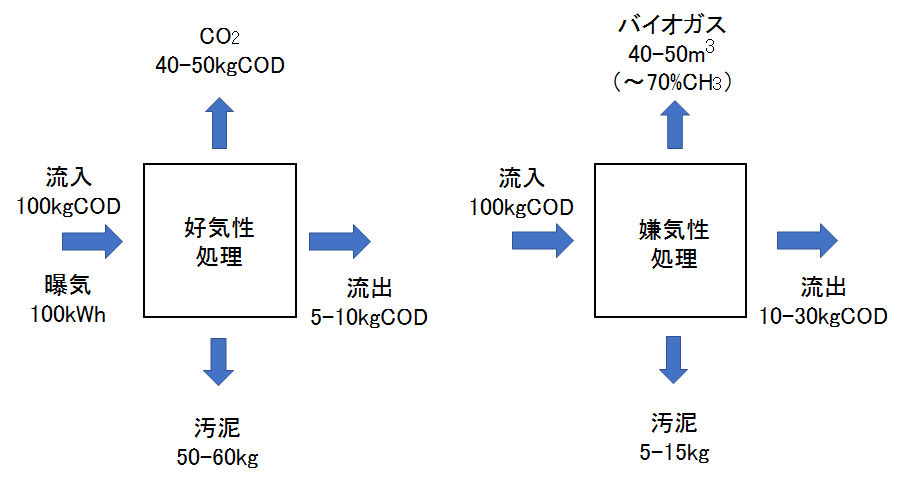
図1 好気・嫌気における物質変換 [Chernicharo, 2007]
Fig.1 Material conversion in aerobic and anaerobic [Chernicharo, 2007].
2.2 有機物の嫌気分解
嫌気性分解では、通性嫌気性菌(好気・嫌気の条件に合わせて生存:
anoxic)および偏性嫌気性菌(嫌気条件でのみ生存:
anaerobic)が共生・関与する逐次および平行する複雑な反応プロセスから構成され、排水・廃棄物中の有機物をメタンや二酸化炭素などの無機物へ変換する。この分解経路は、(1)高分子状有機物の加水分解と可溶化、(2)低分子化と酸生成(発酵)、(3)メタン生成の3つの過程に大別される。
2.2 Anaerobic decomposition of organic matter
Anaerobic digestion is composed of sequential and parallel complex reaction processes in which facultative anaerobes (surviving under aerobic and anaerobic conditions: anoxic) and obligate anaerobes (surviving only under anaerobic conditions:
anaerobic) coexist and participate. It converts the organic substances in wastewater and waste to inorganic substances such as methane and carbon dioxide. This degradation pathway is roughly divided into three processes: (1) hydrolysis and solubilization of polymeric organic substances, (2) reduction of molecular weight and acid production (fermentation), and (3) methane production.
(1)加水分解と可溶化
高分子状物質(多くは固形・懸濁状であるタンパク質・炭水化物・脂質)は、微生物の細胞外分泌酵素による加水分解反応により、それぞれ、可溶性のアミノ酸・糖類・高級脂肪酸となり、細胞壁・細胞膜を通過して細胞内へ吸収可能な物質へ変換される。
(1) Hydrolysis and solubilization
Polymeric substances (mostly solid/suspended proteins/carbohydrates/lipids) become soluble amino acids/sugars/higher fatty acids by the hydrolysis reaction of extracellular secretory enzymes of microorganisms, and pass through cell walls/cell membranes. Then, it is converted into a substance that can be absorbed into cells.
(2)低分子化と酸生成(発酵)
微生物の細胞内に取り込まれたアミノ酸・糖類・高級脂肪酸は代謝分解され、低級脂肪酸・アルコールなどを経て、酢酸、水素、二酸化炭素、アンモニア、硫化水素へ変換される。
(2) Lower molecular weight and acid production (fermentation)
Amino acids, saccharides, and higher fatty acids taken into the cells of microorganisms are metabolically decomposed and converted into acetic acid, hydrogen, carbon dioxide, ammonia, and hydrogen sulfide through lower fatty acids and alcohols.
(3)酢酸、水素と二酸化炭素からメタンの生成
酢酸からメタンガスと二酸化炭素および水素・二酸化炭素からメタンガスが生成する。一般に、有機物の嫌気性分解では(1)の加水分解反応は遅く、固形・懸濁物質や脂質を含む排水では、この過程が律速段階となる。
また、酸性生成速度はメタン生成速度よりも大きいことから、易分解性有機物が急激にかつ大量に投入されると酸生成の促進によって有機酸が蓄積するので、嫌気性処理ではメタン生成速度との均衡がとれるよう有機物負荷を維持することが重要である。さらに、メタン生成菌(偏性嫌気性菌)は環境条件や阻害物質の影響を受けやすいので、メタン発酵を円滑にするためには、ガス生成プロセスの管理に留意することが重要である。
(3) Production of methane from acetic acid, hydrogen and carbon dioxide
Methane gas is produced from acetic acid and from hydrogen and carbon dioxide. Generally, the hydrolysis reaction of (1) is slow in the anaerobic decomposition of organic substances, and this process is the rate-determining step in wastewater containing solid/suspended substances and lipids.
In addition, since the acid production rate is higher than the methane production rate, when a readily degradable organic substance is rapidly and massively added, the organic acid accumulates due to the promotion of acid production. It is important to maintain the organic load so that it is balanced. Furthermore, since methanogens (obligate anaerobes) are easily affected by environmental conditions and inhibitors, it is important to pay attention to the control of the gas generation process in order to facilitate methane fermentation.
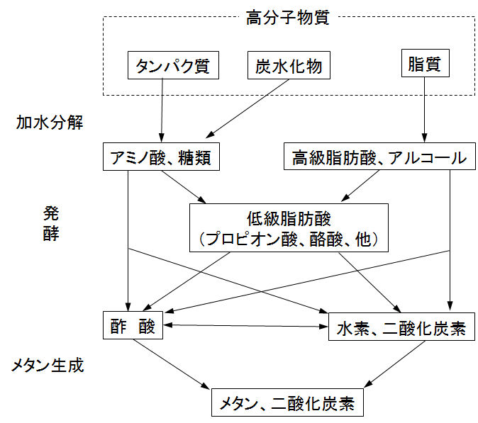
図2 有機性高分子物質の嫌気分解 [Gujer & Zehnder, 1983]
Fig.2 Anaerobic decomposition of organic polymer [Gujer & Zehnder, 1983].
2.3 反応条件
(1)温度
嫌気性処理において、反応槽の温度は極めて重要な操作因子である。嫌気性細菌には、最適な温度条件が二つあり、30~35℃の中温菌と50~60℃の高温菌がある。高温菌は中温菌よりも25~50%程度速い。温度がおよそ20℃以下では、メタン発酵速度が急速に低下する。
2.3 Reaction conditions
(1) Temperature
In the anaerobic treatment, the temperature of the reaction tank is a very important operating factor. There are two optimum temperature conditions for anaerobic bacteria: mesophilic bacterium of 30 to 35°C and thermophilic bacterium of 50 to 60°C. Thermophilic bacteria are 25 to 50% faster than mesophilic bacteria. At temperatures below about 20°C, the methane fermentation rate decreases rapidly.
(2)pH
至適pHは、酸生成菌は5~6、メタン生成菌は6.8~7.2である。メタン生成菌はpH依存性が極めて高く、pH6以下及びpH8以上では急速に活性が低下する。
(2) pH
The optimum pH is 5-6 for acid-producing bacteria and 6.8-7.2 for methanogenic bacteria. Methanogens are extremely pH-dependent, and their activities rapidly decrease at pH 6 and below and pH 8 and above.
(3)栄養塩類
嫌気性菌は好気性菌に比べて、増殖収率が低いので、栄養塩類の必要量も少ないが、不足している場合には、添加する。COD:N:P比として高負荷運転(0.8kg~1.2kgCOD/kgVSS/d)では350:7:1、低負荷運転(0.5kgCOD/kgVSS/d以下)では1000:7:1とされる。適正なN/P比では約7、C/N比は最低25とされる。
(3) Nutrients
Since anaerobic bacteria have a lower growth yield than aerobic bacteria, the required amount of nutrient salts is also small, but if they are insufficient, they are added. The COD:N:P ratio is 350:7:1 for high load operation (0.8kg to 1.2kgCOD/kgVSS/d) and 1000:7:1 for low load operation (0.5kgCOD/kgVSS/d or less). The proper N/P ratio is about 7, and the C/N ratio is at least 25.
(4)阻害物質
メタン生成菌にとって阻害物質の主なものはアンモニアと低級有機酸である。両者とも遊離態(電離していない非イオン体)が反応を阻害する。
低級脂肪酸は嫌気性処理における生成物であり酢酸・プロピオン酸・酪酸などである。酢酸として2,000mg/L以上蓄積すると発酵が阻害される。運転指標として有機酸濃度/アルカリ度を0.3~0.4以下に保つ必要があり、0.8以上では機能障害を起こす。
アンモニアは高pHまたは高温域で遊離しやすいことから、これらの環境でアンモニア阻害を受けやすい。通常の運転条件下では、NH3-N濃度は中温菌では3,500mg/L以上、高温菌では2,000mg/L以上でメタン生成に阻害が起こる。
(4) Inhibitor
The main inhibitors for methanogens are ammonia and lower organic acids. In both cases, the free state (non-ionized nonionic body) inhibits the reaction to do.
Lower fatty acids are products of anaerobic treatment, such as acetic acid, propionic acid, and butyric acid. Accumulation of 2,000 mg/L or more as acetic acid inhibits fermentation. It is necessary to keep the organic acid concentration/alkalinity at 0.3 to 0.4 or less as an operation index, and if it is 0.8 or more, a functional disorder will occur.
Ammonia is likely to be liberated at high pH or high temperature, and is therefore susceptible to ammonia inhibition in these environments. Under normal operating conditions, the NH3-N concentration is 3,500 mg/L or more for mesophilic bacteria and 2,000 mg/L or more for thermophilic bacteria, which inhibits methanogenesis.
(5)硫黄・窒素酸化物
排水中に硝酸(NO3-)、亜硝酸(NO2-)、硫酸(SO42-)、亜硫酸(SO32-)などの無機酸化物塩が多量に存在すると、有機物への電子受容体となり、窒素還元菌や硫黄還元菌が有機物を酸化してアンモニア(NH3)や硫化水素(H2S)やを生成し、メタンガスの発生量が減少するとともに排水中のCOD除去率も減少する。
硫化水素はメタン菌への阻害物質になるとともに、悪臭の発生や装置材料の腐食の原因となる。
(5) Sulfur and nitrogen oxides
Nitric acid (NO3-), nitrous acid (NO2-), sulfuric acid (SO42-), sulfurous acid (SO32-) and other inorganic oxide salts are present in large amounts, they act as electron acceptors for organic substances and nitrogen- and/or sulfur-reducing bacteria grow up, resulting in that the bacteria oxidize organic matters to produce ammonia (NH3) ano/or hydrogen sulfide (H2S) ,and that the amount of methane gas generated is reduced and also the COD removal rate also decreases.
Hydrogen sulfide becomes an inhibitory substance for methane bacteria and causes a bad odor and corrosion of equipment materials.
2.4 生物化学と物質収支
(1)生物化学とCOD
二クロム酸カリウムによる酸素要求量(CODCr)の測定ではほぼ完全に有機物を分解できるので、嫌気性生物反応においては、有機物の指標としてCODCr(本ページではCODと略称する)が用いられる。有機物CnHaObのCODは、完全に化学酸化されるものとすると、次の反応式から求めることができる。
2.4 Biochemistry and material balance
(1) Biochemistry and COD
Because oxygen demand (CODCr) measured by potassium dichromate can decompose organic matter almost completely, CODCr (abbreviated as COD on this page) is used as an index of organic matter in anaerobic biological reactions. The COD of the organic matter CnHaOb can be calculated from the following reaction formula, assuming that it is completely chemically oxidized.
CnHaOb + (1/4)(4n+1-2b)O2→nCO2 + (a/2)H2O
CODT = 8(4n+a-2b)/(12n+a+16b)[gCOD/gCnHaOb]
CnHaObNd + (n+a/4-b/2-3d/4)O2 → nCO2 + (a/2-3d/2)H2O + dNH3
CODT = 8(4n+a-2b-3d)/(12n+a+16b+14d)[gCOD/gCnHaObNd]
(2)生物化学とバイオガス発生
有機物CnHaObNdが完全に生物分解性で、嫌気性生物によりすべてCH4、CO2およびNH3に変換されるものとし、汚泥生成を考慮しないとき、理論的なバイオガスVTおよびメタンガスVCH4の発生量は、次の反応式から推定することができる。
(2) Biochemistry and biogas generation
When the organic matter CnHaObNd, which is completely biodegradable by anaerobic organisms, shall be converted to CH4, CO2 and NH3 and the sludge generation is not considered, the theoretical generation amounts of total biogas VT and methane gas VCH4 can be estimated from the following reaction equation.
CnHaObNd + (n-a/4-b/2+3d/4)H2O →
(n/2+a/8-b/4-3d/8)CH4 + (n/2-a/8+b/4+3d/8)CO2+dNH3
VT ={(n/2+a/8-b/4-3d/8) + (n/2-a/8+b/4+3d/8)}RT/p[L/gCnHaObNd]
VCH4 = (n/2+a/8-b/4-3d/8)/(12n+a+16b+14d)RT/p[L/gCnHaObNd]
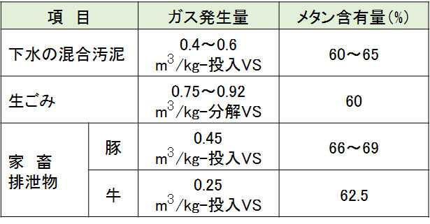
具体的なバイオガス発生量として、表1に各基質について、表2に各固形廃棄物についての測定値の事例を示す。
As specific biogas generation amounts, Table 1 shows examples of measured values for each substrate, and Table 2 shows measured values for each solid waste.
Table 1 Amount of gas generated per 1g of substrate [Kataoka, 2010].
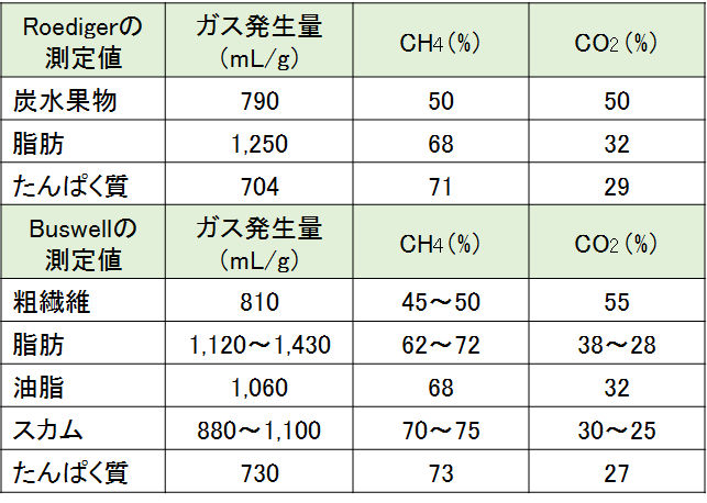
Table 2 Amount of gas generated during methane fermentation of solid organic waste [Ministry of Land, Infrastructure, Transport and Tourism, 2003].
(3)COCによる物質収支
1)分解プロセスでのCOC収支
嫌気性生物分解プロセスに流入するCOD収支を概略すると、次のようになる。
①流入水中の汚濁物質CODinfは分解性成分CODbdと非分解性成分CODrecに分けられる。②CODbdは微生物体内に取り込まれ、微生物の細胞合成分CODcelと細胞外へ放出される代謝産物成分CODint(主として低級脂肪酸)となる。③CODintの一部はメタン生成分CODCH4となり、④CODcelとCODCH4が流入水から除去される成分CODremとなり、HRT内でメタンに変換されないCODintはCODrecとともに系外へ放流される成分CODunとなる。
(3) Mass balance by COC
1) COC balance in the decomposition process
An outline of the COD balance that flows into the anaerobic biodegradation process is as follows.
① The pollutant CODinf in the inflow water is divided into degradable components CODbd and non-degradable components CODrec. ② CODbd is taken up by the microbial body, which is converted into two fractions: CODcel is a cell synthetic component of the microorganism and CODint is metabolite component released to the outside of the cell (mainly lower fatty acids). ③ A part of CODint becomes methane production CODCH4. ④ CODcel and CODCH 4 are the component CODrem those are removed from the inflow water, and CODint that is not converted to methane within the HRT becomes CODun, which is a component released to the outside of the system together with CODrec.
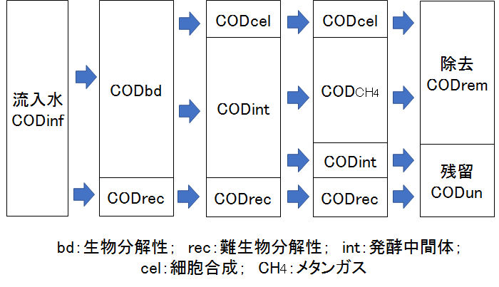
図3 嫌気性分解プロセスにおけるCOD収支 [Chernicharo, 2007]
Fig.3 COD balance in anaerobic decomposition process [Chernicharo, 2007].
2)流入水のCOD成分
一般的に生活・産業に伴う排水中の汚濁物質には固形成分が多く含まれており、加えて生物分解の過程で微生物の細胞合成が行われる。流入水中CODinfは、水質分析において一般的に3つのタイプに分類される [Chernicharo, 2007]。
① ろ過性COD(CODfilt)は、排水を孔径(1.5μm*)のろ紙を通過したろ液中のCOD成分である。または、遠心分離(5,000rpmで5分間)したときの上澄み液中のCOD成分である。CODfilには、溶解成分CODsolとコロイド状成分CODcolを含み、後者はろ紙では分離できない。
② 粒子状COD(CODpart)は粒子状(懸濁状)有機物質のCODでろ紙上に残留する成分で、流入CODinfからCODfilを除いた成分に対応する。
*)日本での浮遊物質(懸濁物質)SS [昭和46年環境庁告示第59号付表9]は、網目2mmのふるいを通過した試料を孔径1μmのガラス繊維ろ紙でろ過したときに、ろ紙上に補足される物質で、水洗後、105~110℃で2時間加熱乾燥し、デシケーター中で放冷後、質量を測定する。また、CODSS(またはCODpart)測定におけるろ紙の孔径は、実験者・研究者によって異なるので、孔径を明記することに留意する。
2) COD component of inflow water
In general, pollutants in wastewater associated with daily life and industry contain a large amount of solid components, and in addition, microbial cell synthesis is performed during the process of biodegradation. CODinf in the influent is generally classified into three types in water quality analysis [Chernicharo, 2007].
① Filterable COD (CODfilt) is a COD component in the filtrate obtained by passing wastewater through a filter paper having a pore size (1.5 μm*). Alternatively, it is the COD component in the supernatant after centrifugation (5,000 rpm for 5 minutes). CODfil contains dissolved component CODsol and colloidal component CODcol, which cannot be separated by filter paper.
② Particulate COD (CODpart) is a COD of a particulate (suspended) organic substance that remains on the filter paper and corresponds to the component obtained by removing CODfil from the inflow CODinf.
*) Suspended solids (suspended solids) in Japan [Showa 46, Environment Agency Notification No. 59, Appendix 9] is a filter paper when a sample that has passed through a 2 mm mesh sieve is filtered through glass fiber filter paper with a pore size of 1 μm. After washing with water using the above-supplemented substance, heat-dry at 105-110°C for 2 hours, allow to cool in a desiccator, and measure the mass. Also, note that the pore size of filter paper in CODSS (or CODpart) measurement differs depending on the experimenter/researcher, so be careful to specify the pore size.
3)流入・流出のCOD収支
排水処理の適正な運転・管理において、反応系の物質収支を測定することは極めて重要である [Lier & et al., 2008]。嫌気性生物処理では、前述したように管理指標としてCODが用いられる。図4に示すように、流入水CODinfについて、次の関係式が成立する。
3) COD balance of inflow and outflow
It is extremely important to measure the mass balance of the reaction system in the proper operation and management of wastewater treatment [Lier & et al., 2008]. In the treatment of anaerobic organisms, COD is used as a management index as described above. As shown in Fig.4, the following relational expression holds for the inflow CODinf.
CODinf = CODeff + CODgas + CODsludge
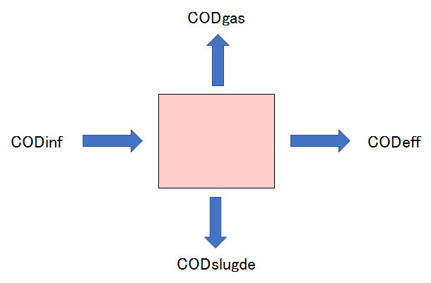
図4 嫌気性反応槽におけるCOD収支
Fig.4 COD balance in anaerobic reactor.
(4)微生物群集の解析
有機物の嫌気性分解とメタンガス発生には、多様な微生物が競争・共生的に関わっている。この複雑な生態系と分解機構を明らかにするため、分子生物学的手法が用いられている [原田・他, 2004]。
分子マーカーとして遺伝子が利用され、16S rRNA遺伝子 [Olsen & et al., 1986] は様々な分野で広く用いられている。また、DGGE(denaturing gradient gel electrophoresis)法 [Muyzer & et al., 1993]、T-RELF(terminal-restriction length polymorphisms)法 [Liu & et al., 1997]、FISH(fluorescence in situ hybridization)法 [Delong & et al., 1989; Amann & et al., 1990] などの技術も開発され、微生物の新しい知見が得られるようになった。
メタン発酵は古細菌(Archaea)と細菌(Bacteria)の両ドメインにまたがる多種多様な微生物から構成され、遺伝子解析により既知の微生物と相同性が高いものから、これまで人為的に培養されていないものや難培養性微生物(鎌形、2007)が多数存在することが明らかとなっている。
遺伝子解析に加え、DNAプローブを用いたin situ hybridization法による検出や定量も進められてきた。特に、グラニュール汚泥は球状の生物膜という特異な構造を有しており、薄片断片化し、FISH法と共集点レーザー走査顕微鏡を用いることで、特定の微生物群の空間分布の把握が可能となった [Sekiguchi, 1999]。
微生物検査[大楠,2012]には、①顕微鏡検査(電子顕微鏡を含む)、②培養検査、③抗原検査、④薬剤感受性試験に加えて、⑤遺伝子検査や⑥質量分析検査などがある。特に、質量分析検査は遺伝子ではなく、例えば、MALDI-TOF MS(Matrix Assisted Laser Desorption/Ionization – Time of Flight Mass Spectrometry)、資料中のタンパク質成分をイオン化(2002年ノーベル賞を受賞した田中耕一博士が発明)して、その質量の違いにより分析するものである。これらの検査は自動化・機器化(キットを含む)されるとともに、データベースも刻々と蓄積されている。
今後、他分野の研究・技術も活用した汚濁物質を浄化する微生物に関わる様々な知見の蓄積により、排水処理分野の研究・技術開発や設計・操作・管理の更なる進展が期待できる。
(4) Analysis of microbial community
Various microorganisms are competing and symbiotically involved in the anaerobic decomposition of organic substances and the generation of methane gas. Molecular biology techniques have been used to clarify this complex ecosystem and degradation mechanism [Harada et al., 2004].
Genes are used as molecular markers, and the 16S rRNA gene [Olsen & et al., 1986] is widely used in various fields. In addition, techniques such as the methods, DGGE (denaturing gradient gel electrophoresis) method [Muyzer & et al., 1993], T-RELF (terminal-restriction length polymorphisms) method [Liu & et al., 1997], and FISH (fluorescence in situ hybridization) [Delong & et al., 1989; Amann & et al., 1990], have also been developed, and new knowledge of microorganisms has been obtained.
Methane fermentation consists of a wide variety of microorganisms that span both archaea (bacteria) and bacterial (bacteria) domains, and genetic analyses have revealed that there are a large number of highly homologous to known microorganisms, those that have not been artificially cultivated so far, or difficult-to-cultivate microorganisms (Kamagata, 2007).
In addition to gene analysis, detection and quantification by the in situ hybridization method using a DNA probe have been advanced. In particular, granule sludge has a peculiar structure of spherical biofilm, and it is possible to grasp the spatial distribution of a specific microbial group by fragmenting thin pieces and using the FISH method and the co-focusing laser scanning microscope [Sekiguchi, 1999].
Microbial tests [Okusu, 2012] include ① microscopy (including electron microscopy), ② culture testing, ③ antigen testing, ④ drug susceptibility testing, as well as ⑤ genetic testing and ⑥ mass spectrometry testing. In particular, mass spectrometry is not a gene, but for example, MALDI-TOF MS (Matrix Assisted Laser Desorption/Ionization – Time of Flight Mass Spectrometry), ionization of protein components in materials (invented by Dr. Koichi Tanaka who won the 2002 Nobel Prize), and analyze by the difference in the mass. These tests are automated and instrumented (including kits), and a database is being accumulated every moment.
In the future, we can expect further progress in research and technology development and design, operation, and management in the wastewater treatment field by accumulating various knowledge related to microorganisms that purify pollutants by utilizing research and technology in other fields.
3.嫌気性生物処理技術
3.1 従来技術
(1)嫌気性池(anaerobic pond)
安定化池法[Mara、2003]は、その主な除去対象により、①嫌気性菌により有機物を除去する嫌気性池(anaerobic pond)、②藻類の光合成による酸素発生と水表面からの空気中の酸素補給による好気性微生物と底面・底泥中の嫌気性菌による有機物除去する通性池(facultative pond)、および③病原菌を除去する熟成池(mauration pond)の3つに大別される。上記池の単独または組合わせ、あるいは、他法との組合わせによって排水処理が実施されている。同じタイプの安定化池であっても、地域や利用目的によって、設計・運転・管理条件が大きく異なるので留意する必要がある。
通常、上記池①~③の組合せの初段として使われることが多い。嫌気性池は深くて(少なくとも2~3m、2~5mが一般的)大きな貯留池で、嫌気的な微生物分解と沈降分離を目的とする。汚水源の種類、有機物濃度や温度、また、後段処理の有無や処理水の再利用などにより、滞留日数が大きく異なる。生活排水の一次処理では、滞留日数は1~10日で運転される。し尿を含む排水には病原菌が含まれていることが多く、長い滞留日数で運転するか、熟成池などによる除菌が必要となるので、灌漑利用や公共水域へ放流においては、注意が必要である。沈降・蓄積した汚泥の除去が必要で、除去汚泥は農地に散布しても臭気の問題はない。適正な設計と適正な汚水の流入ならば、汚泥の引抜きはそれほど高い頻度ではない(数年に1回程度)が、汚泥が蓄積しすぎると正常な浄化ができない。
池は、地下水汚染防止のため遮水、周辺表漂流水の流入防止のための盛土、事故防止のための安全柵の設置などの対策が必要である。悪臭や昆虫の発生などの問題があり、場所の設定には注意が必要である。
3. Anaerobic biological treatment technology
3.1 Conventional technology
(1) Anaerobic pond
Stabilization pond method [Mara, 2003] mainly consists of ① an anaerobic pond that removes organic matter by anaerobic bacteria, ② oxygen generation by photosynthesis of algae and air from the water surface. There are three major categories: facultative ponds that remove aerobic microorganisms due to supplemental oxygen and anaerobic bacteria in the bottom/bottom mud, and ③ mauration ponds that remove pathogens. Wastewater treatment is carried out by the above ponds alone or in combination, or in combination with other methods. It is necessary to keep in mind that even the same type of stabilization pond has large differences in design, operation, and management conditions depending on the area and purpose of use.
Usually, it is often used as the first stage of the combination of the above ponds ① to ③. Anaerobic ponds are deep, large (generally at least 2-3 m, 2-5 m) large reservoirs intended for anaerobic microbial degradation and sedimentation. The number of retention days varies greatly depending on the type of wastewater source, the concentration of organic substances and temperature, the presence or absence of post-treatment, and the reuse of treated water. In the primary treatment of domestic wastewater, the operation period is 1 to 10 days. Since wastewater including human waste often contains pathogenic bacteria, it is necessary to operate for a long period of time or disinfect by aging ponds, etc., so care must be taken in irrigation use and discharge to public water areas. It is necessary to remove the sludge that has settled and accumulated, and even if the removed sludge is sprayed on farmland, there is no odor problem. With proper design and proper inflow of sewage, sludge extraction is not very frequent (every few years), but if too much sludge accumulates, normal purification cannot be achieved.
For the pond, it is necessary to take measures such as impermeable water to prevent groundwater pollution, embankment to prevent inflow of drift water around the pond, and installation of safety fences to prevent accidents. There are problems such as foul odors and generation of insects, so it is necessary to be careful when setting the location.
(2)嫌気消化(anaerobic digesters)
下水汚泥やし尿を嫌気性消化すると、脱離液、消化汚泥、消化ガスの3成分に分けることができる。初期に見られた消化槽(腐敗槽、トラビス槽、イムホフ槽:図5a-c)は消化と沈殿を兼ね備えた単槽式であるが、その後、加温、撹拌(消化ガスや機械による撹拌)、2槽式、分離消化汚泥の返送などにより、処理の効率化が行われた。
腐敗槽(spectic tank)は構造が簡単で電力が不要であり、各家庭や下水システムのない小さな集落からの生活排水の一次処理法として、今日においても、世界各地(特に電力供給のない、または、少ない地域)で広く利用されている。
(2) Anaerobic digesters
Anaerobic digestion of sewage sludge and night urine can be divided into three components: desorbed liquid, digested sludge, and digested gas. The digestion tanks found in the early stages (a septic tank, a travis tank, and an Imhoff tank: Fig. 5a-c) are single tanks that combine digestion and precipitation, but after that, heating and stirring (by digestion gas and mechanical agitation), 2-tank system, returning separated digested sludge, etc., to improve the efficiency of treatment.
Spectral tanks have a simple structure and do not require electricity, and as a primary treatment method for domestic wastewater from individual households and small settlements without sewage systems, they are still used today in many parts of the world (especially when there is no electricity supply or in a small ruaral area).
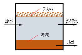
図5a 腐敗槽
Fig.5a Septic tank.
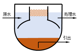
図5b トラビス槽
Fig.5b Travis tank.
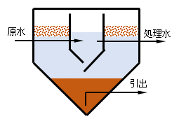
図5c イムホフ槽
Fig.5c Imhoff tank.
1)標準消化槽(conventional digester)
密封槽に消化汚泥などの種汚泥を満たし、30~37℃に加温しながら下水汚泥やし尿を反連続的に投入し、20~30日のHRTで処理する。常温消化では60~70日で処理する。
一般的には、消化槽は2段直列に配置し、第1槽は消化ガスの吹き込みにより攪拌し、投入有機物1kg当たり0.4~0.5m3の消化ガスが発生する。第2槽は消化を完全に進めるとともに固液分離を行い、ガス発生量は第1槽の1/20程度となる。汚泥消化における有機物負荷は30℃では1.5kg-VS/m3/である。高温消化(50~60℃)では、消化日数が10~15日に短縮できる。
1) Standard digester
Fill the sealed tank with seed sludge such as digested sludge, and while heating to 30-37℃, add sewage sludge and night urine anti-continuously and treat with HRT for 20-30 days. It takes 60 to 70 days to digest at room temperature.
Generally, the digestion tanks are arranged in two stages in series, and the first tank is agitated by blowing in the digestion gas, and 0.4 to 0.5 m3 of digestion gas is generated per 1 kg of organic matter input. The second tank completes the digestion and performs solid-liquid separation, and the gas generation amount is about 1/20 of the first tank. The organic matter load in sludge digestion is 1.5 kg-VS/m3/ at 30℃. With high temperature digestion (50-60°C), the digestion days can be shortened to 10-15 days.
2)高率消化槽(high-rate anaerobic digester)
高率消化は、消化ガス攪拌や機械攪拌により消化槽内の混合液を連続的に攪拌することで、HRTを6~8.7日程度まで短縮でき、有機物負荷を3~5kg-VSS/m3/dに高められる。連続攪拌により、(a)槽内温度の均一化、(b)投入基質と消化汚泥の十分な混合、(c)スカム発生の防止、(e)短絡流発生による局部的な高濃度域の防止、などに大きな効果をもつ。
2) High-rate anaerobic digester
For high-rate digestion, HRT can be shortened to about 6 to 8.7 days by continuously stirring the mixture in the digester tank by digestion gas stirring or mechanical stirring, and the organic load can be increased to 3 to 5 kg-VSS/m3/d. To be continuous agitation, which has a great effect on, ensures (a) uniform temperature inside the tank, (b) sufficient mixing of input substrate and digested sludge, (c) prevention of scum, and (e) prevention of localized high concentration area due to short-circuit flow.
3)嫌気性接触法(anaerobic contact process)
消化流出液を沈殿分離して回収した消化汚泥を流入液と混合して消化槽へ返送する方法で、活性汚泥法を嫌気性処理へ適用した方式である。
これにより消化槽内の菌体濃度を高く保持しHRTを短縮できる。一方、メタン生成菌はフロックを形成せず、消化汚泥は沈降性が悪いので汚泥分離が難しく系外へ流失しやすいことを考慮する必要がある。本法は、好気性処理では高負荷となる高濃度有機性排水に適している。
3) Anaerobic contact process
This is a method in which the digested sludge recovered by sedimentation of the digested effluent is mixed with the influent and returned to the digestion tank, and the activated sludge method is applied to anaerobic treatment.
This makes it possible to maintain a high bacterial cell concentration in the digestion tank and shorten HRT. On the other hand, it is necessary to consider that methanogens do not form flocs and digested sludge has poor sedimentation properties, making sludge separation difficult and easy to flow out of the system. This method is suitable for high-concentration organic wastewater that has a high load in aerobic treatment.
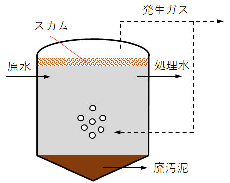
図6a 標準消化槽
Fig.6a Standard digester.
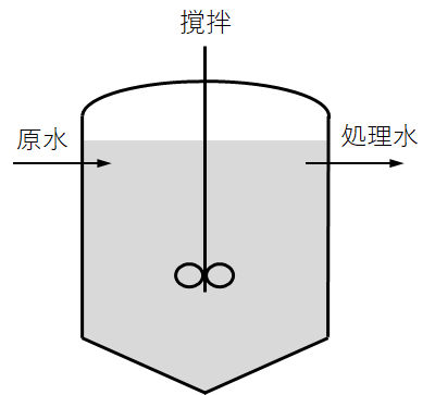
図6b 高率消化槽
Fig.6b High rate digestion tank.
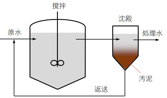
図6c 嫌気性接触法
Fig.6c Anaerobic contact method.
3.2 微生物保持と高速化技術
汚泥滞留時間を水理学的滞留時間に関係なく制御し、反応槽内に微生物を高濃度に維持し有機物の容積負荷を高くして処理時間を短縮する方法として、担体固定化法とグラニュール法に大別できる。
3.2 Microorganism retention and rate-up technology
As a method of controlling the sludge retention time regardless of the hydraulic retention time, maintaining a high concentration of microorganisms in the reaction tank and increasing the volume load of organic substances to shorten the treatment time, that is sludge immobilization in the reactor which can be roughly divided into the use of carrier or granule formation.
(1)担体固定法(attached bacterial processes)
嫌気性生物処理では、安定な処理性能の確保と高負荷処理のため、比増殖速度の小さいメタン生成菌を反応槽内に高濃度に保持する必要がある。そのため、微生物固定化方式と呼ばれる高負荷型嫌気性処理法が産業排水分野を中心に実用化された。
(1) Attached bacterial processes
In the treatment of anaerobic organisms, it is necessary to maintain a high concentration of methanogens having a low specific growth rate in the reaction tank in order to ensure stable treatment performance and high load treatment. Therefore, a high-load type anaerobic treatment method called a microorganism immobilization method has been put to practical use mainly in the industrial wastewater field.
1)固定床(fixed bed anaeroic reactor)
密封した反応槽内部にプラスチックや砕石など担体を充填し、その表面に嫌気性菌の生物膜を付着増殖させて排水と接触する方法で処理を行う。
充填材の種類・サイズ・流れ方向(上昇流、下降流)などによって様々な方式がある。一方、担体充填によって反応槽の実容積の減少、投入排水中の懸濁物や担体表面での無機物の晶析などによる反応槽の閉塞や発泡などの問題がある。
1) fixed bed anaeroic reactor
The inside of the sealed reaction tank is filled with a carrier such as plastic or crushed stone, and a biofilm of anaerobic bacteria is attached to and proliferated on the surface of the carrier, and the treatment is performed by contacting with waste water.
There are various methods depending on shape and size of the carrier, and flow direction of the water (upward or downward) through the filler. On the other hand, there is a problem that the actual volume of the reaction tank is decreased by filling the carrier, and the reaction tank is clogged or foamed due to crystallization of suspended matter in the input drainage or crystallization of inorganic substances on the carrier surface.
2)流動床(expanded/fluidised bed reactor)
粒径0.2~1.0mm程度の砂、アンスラサイト、軽量骨材などの粒状付着担体を流動状態に浮遊させ、その表面に嫌気性菌を付着・増殖させる方法で処理を行う。流動床では閉塞の問題がなく、排水との接触効率も高く、低濃度まで基質を分解できる。一方、スケールアップが比較的に難しく、担体流動のための動力費、粒子間の摩擦による生物膜の剥離、担体流出などの課題がある。また、担体を反応槽内に均一に浮遊させるための流動条件の維持が難しい。
2) Fluidized bed (expanded/fluidised bed reactor)
A granular adhering carrier such as sand, anthracite, and lightweight aggregate having a particle size of 0.2 to 1.0 mm is suspended in a fluidized state, and anaerobic bacteria adhere to and grow on the surface of the carrier. In the fluidized bed, there is no problem of clogging, the contact efficiency with waste water is high, and the substrate can be decomposed to a low concentration. On the other hand, scale-up is relatively difficult, and there are problems such as power cost for carrier flow, separation of biofilm due to friction between particles, and carrier outflow. Further, it is difficult to maintain the flow condition for uniformly suspending the carrier in the reaction tank.

図7a 嫌気性固定床法
Fig.7a Anaerobic fixed bed method.
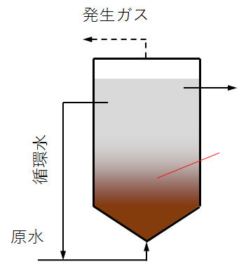
図7b 嫌気性流動床法
Fig.7b Anaerobic fluidized bed method.
(2)グラニュール法
1)UASB(Upflow Anaerobic Sludge Bed)
凝集・集塊機能を有する粒径0.5~2.0mm程度の沈降性の優れたグラニュール(粒状)を形成した嫌気性菌汚泥を反応槽に保持する方法である。高負荷処理が可能で汚泥層の閉塞も起こらないことから、中・高濃度排水処理法とし普及している。排水は底部から投入され、汚泥層を上昇する過程でグラニュールと接触して有機物が分解される。これを上向流嫌気性汚泥床(UASB:Up-flow Anaerobic Sludge Blanket)法という。
UASB反応層の構造は、反応層底部に原水供給装置、上部に気液固分離装置(GLSS:Gass-Liguid-Solid Separator)を設置している。排水を反応層底部から均一に流入させる。一般的には、流入水の上昇速度は最大5m/h、容積負荷最大15kg/m3/dで運転される。
(2) Granule method
1) UASB (Upflow Anaerobic Sludge Bed)
This is a method of holding anaerobic bacterial sludge in the reaction tank, which has granules (granulate) having a particle size of 0.5 to 2.0 mm and having a coagulation/agglomeration function and having excellent sedimentation properties. It is widely used as a medium/high-concentration wastewater treatment method because it enables high-load treatment and does not cause clogging of the sludge layer. Wastewater is introduced from the bottom, and in the process of rising in the sludge layer, it contacts the granules to decompose organic matter. This is called the Up-flow Anaerobic Sludge Blanket (UASB) method.
As for the structure of the UASB reaction layer, a raw water supply device is installed at the bottom of the reaction layer and a gas-liquid solid separation device (GLSS: Gass-Liguid-Solid Separator) is installed at the top. The waste water is allowed to flow evenly from the bottom of the reaction layer. Generally, the rising speed of the inflow water is 5 m/h at maximum and the volume load is 15 kg/m3/d at maximum.
2)EGSB(Expanded Granular Sludge Bed
UASB法の高負荷改良型として、膨張汚泥床(EGSB:Expanded Granular Sludge Bed)法がある。流入水を高い上昇速度(5~10m/h)で運転しグラニュール床を膨張させ、流入水とグラニュールの接触効率を改善し、処理効率を増加している。
通常のUASB法によりも2~3倍以上の高負荷処理能力(30~40kgCOD/m3/d)を可能にしている。EGSB法では、反応槽の高さ/断面積の比を大きく設定する。流出水の一部を流入水へ返送し反応槽内を循環する方式や安定した固液分離を行うためにGLSSを多段に設置した方式もある。
2) EGSB (Expanded Granular Sludge Bed
There is an expanded sludge bed (EGSB) method as a high load improvement type of the UASB method. The inflow water is operated at a high rising speed (5 to 10 m/h) to expand the granule bed, improving the contact efficiency between the inflow water and the granule and increasing the treatment efficiency.
Even with the normal UASB method, high load processing capacity (30-40kgCOD/m3/d) more than 2-3 times is possible. In the EGSB method, the ratio of the height/cross-sectional area of the reaction tank is set large. There is also a system in which a part of the outflow water is returned to the inflow water and circulated in the reaction tank, and a system in which GLSS is installed in multiple stages for stable solid-liquid separation.
3)IC(Internal Circulation Reactor)
IC反応槽は、垂直に接続したUASB構造を有する上下2段の反応部から構成される。
反応槽底部から導入された減水中の有機物の大半は下部反応部でバイオガスに変換される。このバイオガスは分離器で収集される。この分離器と上部の反応器の気液分離器はパイプ(上昇パイプ)で接続されており、ガスリフト効果によって混合液も上昇する。気液分離器の底部には下降パイプが下部反応器に接続されており、ガスが系外に排出されるとともに、混合液は下部反応器へ返送される。このようにして、混合液が反応槽内部で自然循環する構造となっている。
下部反応部の処理液は、上部反応部へ導入され残存する分解性有機物がガス化されて、処理液は系外へ排出される。この反応部での混合液の上昇速度は2~10m/hに設定される。
以上のような方法により、UASBよりも高負荷・高速(35~50kgCOD/m3/h、HRT < 2.5h)に有機物の嫌気性分解が可能となる。IC反応槽は、懸濁物質を含む高濃度の有機性産業排水へ普及している。
3) IC (Internal Circulation Reactor)
The IC reaction tank is composed of two vertically connected reaction sections having a UASB structure connected vertically.
Most of the organic matter in the reduced water introduced from the bottom of the reaction tank is converted into biogas in the lower reaction section. This biogas is collected in a separator. This separator and the gas-liquid separator of the upper reactor are connected by a pipe (a rising pipe), and the mixed liquid also rises due to the gas lift effect. At the bottom of the gas-liquid separator, a descending pipe is connected to the lower reactor so that the gas is discharged out of the system and the mixed liquid is returned to the lower reactor. In this way, the mixed solution is naturally circulated inside the reaction tank.
The treatment liquid in the lower reaction section is introduced into the upper reaction section, the remaining decomposable organic substances are gasified, and the treatment solution is discharged out of the system. The rising speed of the mixed solution in this reaction section is set to 2 to 10 m/h.
By the above method, anaerobic decomposition of organic substances can be performed at higher load and speed (35 to 50 kg COD/m3/h, HRT < 2.5h) than UASB. IC reactors are popular for high-concentration organic industrial wastewater containing suspended solids.
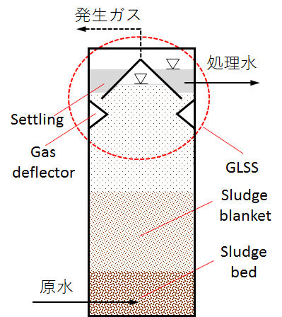
図8a UASB法
Fig.8a UASB method.
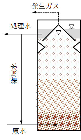
図8b EGSB法
Fig.8b EGSB method.
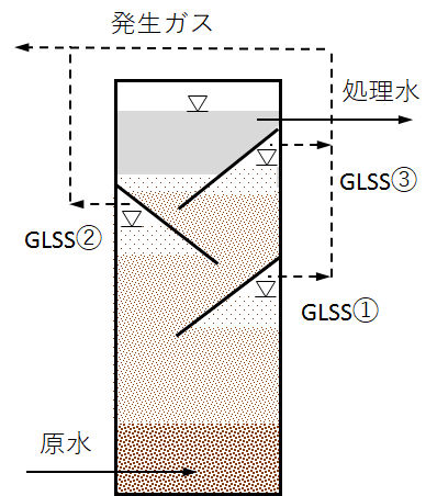
図8c 多段式EGSB法
Fig.8c Multi-stage EGSB method.
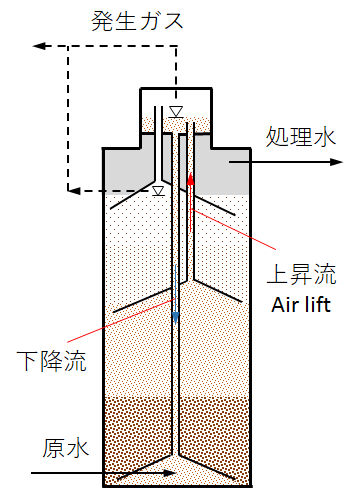
図8d IC法
Fig.8d IC method.
4)グラニュール汚泥の特性と運転操作
UASB法では、グラニュール汚泥を槽内に維持し継続的に増殖させることが最重要である。そのためにUASB処理槽内でメタン生成菌が優先的に増殖できる環境を作る必要があり、特に、グラニュール汚泥の骨格を形成し、かっつ酢酸を唯一の基質として増殖するMetanosaeta属のメタン生成菌の増殖が不可欠である。正常なグラニュール汚泥は、糸状性あるいはロッド状のMetanosaeta属のメタン生成菌が絡み合った構造である。
一方、Metanosarcina属のメタン生成菌の汚泥の粒径は概ね0.5mm以下と小さく流出しやすくなり、処理水質も悪化することから、このタイプのグラニュール汚泥の異常繁殖は望ましくない。傾向として、高酢酸濃度下でMetanosarcina属メタン生成菌が優先となることが多い(詳しくは、文献[例えば、Lier, 2008, pp.408-409や片岡,2010など]を参照)。
グラニュール汚泥の生成・保持において、原水中の懸濁粒子の挙動に注意する必要がある。SS成分がグラニュール汚泥に付着したり、反応槽内に残留・蓄積すると、処理性能が低下する。また、SS成分を包括する形でグラニュール汚泥が形成されると、これが有機性SSであると、時間経過とともにこのSS成分が徐々に可溶化分解して空隙を生じ、ここにガスが蓄積してグラニュール汚泥の浮上の原因となる。UASBの前段で原水中のSSを除去する対策が必要となる。
UASB反応槽内でメタン生成菌が優先的に増殖できる環境作りのために、酸生成槽をUASB反応槽の前段に設置して、酸生成菌の基質がUASB反応槽内に直接流入しないようにして、酸生成菌の増殖量を制限する方法もある。また、酸性生成槽へUASB処理水を循環することで、酸生成菌の連続的な植種を行うとともに、酸生成槽でのpH低下を防ぎ、低級脂肪酸によるメタン生成菌への阻害を緩和することができる。
4) Characteristics and operation of granule sludge
In the UASB method, it is of utmost importance to maintain granule sludge in the tank and continuously grow it. Therefore, it is necessary to create an environment in which the methanogens can grow preferentially in the UASB treatment tank, and in particular, the methanogens of the genus Metanosaeta that form the skeleton of granule sludge and grow with bromine acetate as the only substrate. Proliferation is essential. Normal granule sludge has a structure in which filamentous or rod-shaped Methanogens of the genus Metanosaeta are intertwined.
On the other hand, the sludge size of Methanogens of the genus Metanosarcina is as small as 0.5 mm or less, which facilitates the outflow and deteriorates the quality of treated water. Therefore, abnormal growth of this type of granule sludge is not desirable. As a tendency, Metanosarcina sp. methanogens have a high priority under high acetic acid concentration (for details, see the literature [eg, Lier, 2008, pp.408-409 and Kataoka, 2010]).
It is necessary to pay attention to the behavior of suspended particles in raw water in the production and retention of granule sludge. If the SS component adheres to the granulated sludge or remains/accumulates in the reaction tank, the treatment performance will decrease. Also, when granulated sludge is formed so as to include SS components, if this is organic SS, this SS component gradually solubilizes and decomposes over time to form voids, where gas accumulates. It causes the floating of granule sludge. It is necessary to take measures to remove SS in raw water before the UASB.
In order to create an environment in which methanogenic bacteria can preferentially grow in the UASB reaction tank, install an acid generation tank in front of the UASB reaction tank to prevent the substrate of acid generation bacteria from flowing directly into the UASB reaction tank. Thus, there is also a method of limiting the growth amount of acid-producing bacteria. In addition, by circulating UASB-treated water to the acid production tank, continuous seeding of acid-producing bacteria is performed, pH drop in the acid-producing tank is prevented, and inhibition of methanogenic bacteria by lower fatty acids is mitigated. be able to.
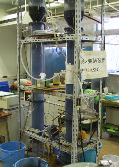
写真1a 室内でのUASB実験の様子
Photo 1a Indoor UASB experiment.
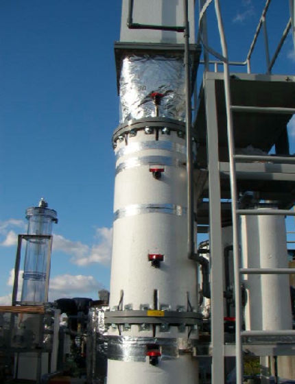
写真1b 屋外でのUASB実証実験の様子
Photo 1b Outdoor UASB demonstration test.
Photo 1 UASB energy recovery from solubilized liquid obtained by hydrolyzing and reducing the molecular weight of mixed sludge from municipal sewage with subcritical water.
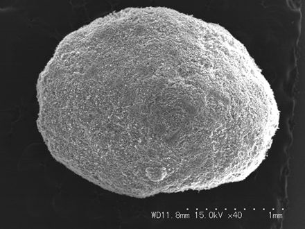
写真2a グラニュール全景; ×40
Photo 2a Overall view of granules; ×40.
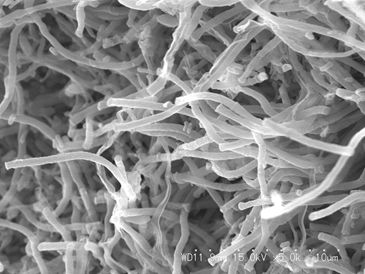
写真2b グラニュール表面; ×5,000
Photo 2b Granule surface; ×5,000.
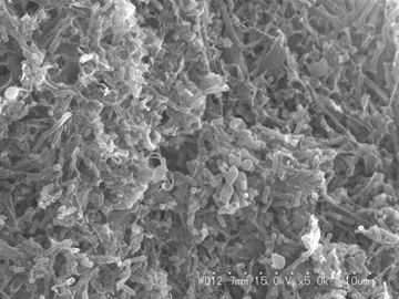
写真2c グラニュール断面; ×5,000
Photo 2c Granule cross section; ×5,000.
Photo 2 Electron micrograph of a typical granule (2-5mm) used in the above UASB experiment (Photo 1).
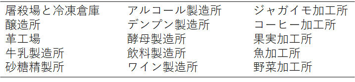
4.応用分野
嫌気性消化法は、農業廃棄物、動物糞尿、下水汚泥、都市廃棄物などの固形有機性廃棄物の処理に広く利用されている。また、嫌気性消化法は、先進国・開発国を問わず農畜産業や食品・飲料工場など(表3)からの排水処理に活用されている。家庭排水についても、熱帯・亜熱帯地域で嫌気性処理技術、特にUASB型のリアクター、の活用が確実に増加している。
生活・産業の各分野の排水処理の具体的な事例は、別のページで詳しく紹介する。
4. Application fields
Anaerobic digestion is widely used for the treatment of solid organic waste such as agricultural waste, animal manure, sewage sludge, and municipal waste. In addition, the anaerobic digestion method is used for wastewater treatment from agricultural and livestock industries, food and beverage factories (Table 3) in both developed and developing countries. As for domestic wastewater, the use of anaerobic treatment technology, especially UASB type reactors, is steadily increasing in tropical and subtropical regions.
Specific examples of wastewater treatment in various fields of life and industry are introduced in detail on another page.
Table 3 Application of anaerobic treatment to main industrial wastewater.
嫌気性処理技術の歴史
嫌気性生物処理は、酸素のない嫌気性環境下で生育する嫌気性菌の代謝作用により、有機物をメタンガスや炭酸ガスに分解する生物処理法である。
嫌気性処理は、19世紀末から20世紀初頭にヨーロッパで始まり、1950年代には加温や機械式撹拌などの処理方式が開発され、国内でも下水汚泥やし尿処理での汚泥減量化・安定化を目的とした嫌気性消化法が普及した。1980年代になると微生物固定化方式による高負荷型嫌気性処理法が産業排水処理分野を中心に普及した。そして現在、低酸素社会に向けた未利用資源の活用技術として、廃棄物系バイオマス向け嫌気性処理法が大きく脚光を浴びている。[片岡, 2010]
History of anaerobic treatment technology
Anaerobic biological treatment is a biological treatment method that decomposes organic matter into methane gas and carbon dioxide by the metabolic action of anaerobic bacteria that grow in an anaerobic environment without oxygen.
Anaerobic treatment began in Europe from the end of the 19th century to the beginning of the 20th century, and treatment methods such as heating and mechanical stirring were developed in the 1950s to reduce and stabilize sludge in sewage sludge and human waste treatment in Japan. The targeted anaerobic digestion method became popular. In the 1980s, the high-load anaerobic treatment method using the microorganism immobilization method became popular mainly in the industrial wastewater treatment field. At present, an anaerobic treatment method for waste biomass is in the spotlight as a utilization technology of unused resources for a low oxygen society. [Kataoka, 2010]
(1)嫌気性処理の始まり
1)ヨーロッパ
14~17世紀のヨーロッパでは、城壁に囲まれた狭い土地に多くの住民が集中し汚泥処理も不潔なまま放置され、流行病にも度々襲われた。1842年イギリスでは、公衆衛生法、河川汚濁防止法が制定され、近代的公衆衛生制度や汚物処理、上下水道などの環境整備が始まった。
1862年フランスの細菌学者Louis Pasteurは、乳酸発酵・アルコール発酵の研究から、酸素存在下で生活する生物を好気性(aerobic)生物、無酸素状態で生活できる生物を嫌気性(anaerobic)生物と呼び、識別するようになった。
嫌気性処理法は、1875年フランスのLouis MourasのAutomatic Scavenger(自動清浄機)が始まりとされる。Louis Mourasは、し尿の固形分が汚水溜めの中で液化・溶解することを見つけ、汚水溜めを密封して、液化分を放流する管を取り付けた。1895年イギリスのDonald Cameronは、嫌気性菌の働きを利用したSeptic Tank(腐敗槽)を開発した。これは、トラップ付きの流入口と出口を備え、両方が下水の水面下に挿入されていることにより、水面上に形成されるスカム槽の破壊を防ぐ浅い槽で、濃縮汚泥は汚泥溜めに受け入れた。
1903年イギリスのWilliam Travisが開発したTravis Tankがハンプトン市に建設され、1906年ドイツのKarl Imhoffが開発したImhoff Tankがエムッシャーで稼働した。これらは二階槽と称され、単層で下水と汚泥を沈降分離して汚泥消化(嫌気性消化)をする。これらの嫌気性処理は、家庭下水法として普及し始めたが、1913年ArdernとLockettが開発した活性汚泥法の台頭によって家庭下水での適用は次第に少なくなり、下水汚泥の減量化・安定化を目的とした嫌気性消化法として展開されていった。
(1) Start of anaerobic treatment
1) Europe
In Europe in the 14th to 17th centuries, many residents were concentrated in the narrow land surrounded by the city walls, sludge treatment was left unclean, and epidemics were frequently attacked. In 1842 in England, the Public Health Law and the River Pollution Control Law were enacted, and the modern public health system, sewage disposal, and environmental improvement such as water and sewerage began.
1862, French bacteriologist Louis Pasteur called and came to identify anaerobic organisms living in the presence of oxygen as aerobic organisms and anaerobic organisms living in the presence of oxygen from the study of lactic acid fermentation and alcoholic fermentation.
The anaerobic treatment method is said to be started in 1875 by Louis Mouras’s Automatic Scavenger in France. Louis Mouras found that the solids of human waste liquefied and dissolved in the sump, sealed the sump, and installed a tube to drain the liquefaction. 1895, Donald Cameron of the United Kingdom developed the Septic Tank that utilizes the action of anaerobic bacteria. This is a shallow tank with an inlet and an outlet with traps, both of which are inserted below the surface of the sewage to prevent destruction of the scum tank formed on the surface of the water.
It was Travis Tank developed by William Travis in England in 1903 was built in Hampton City, and Imhoff Tank developed by Karl Imhoff in Germany in 1906 started operation in Emscher. These are called the second-floor tanks, and sewage and sludge are settled and separated in a single layer for sludge digestion (anaerobic digestion). These anaerobic treatments have started to spread as a domestic sewage method, but with the rise of Activated Sludge method developed by Ardern and Lockett in 1913, these applications in domestic sewage gradually decreased, and these are developed as an anaerobic digestion method for the purpose of reducing and stabilizing sewage sludge.
2)日本
日本では、仏教の影響などから清潔を旨とする習慣があり、汚物処理もくみ取り式で農家の肥料として、諸外国に比べて個人衛生が優れていた。
ところで余談であるが、本サイト編集者の幼い頃(昭和20年代)、古里では、各畑の脇にし尿の安定化槽があり、熟成して肥料として活用されていた。また、食品廃棄物などは納屋の片隅でコンポスト化して、農地の肥料として使っていた。生活雑排水は沈殿槽(滞留日数:2~3日程度)に流入し、固形分を除いて、上澄み液を敷地の脇を流れる小川に放流していた。小川には小魚(フナ、(バラ)タナゴ、ゴリ、シマドジョウなど)、カワニナ、シジミなどが生息していた。夏には、その小川に多数のホタルが舞って、庭先だけでなく家の中にまで飛んできたことを覚えている。その後、化学肥料の普及と生活水準の向上(雑排水の性状変化)に伴い小川・河川の水質悪化が進行し、このような風景は少しずつ消えていった。
さて本論に戻ると、明治初期のコレラなど伝染病流行で、長與専齋(ながよせんさい、1875年内務省衛生局初代局長)は衛生工事を推進し、公衆衛生思想が普及し始めた。そして、中島鋭治(東京大学教授、東京市技師長)が1901年8月~1802年欧米各都市の上下水道や土木事業を調査し、前述したSeptic Tank(腐敗槽)の技術が日本に伝わった。
そして、1930年10月に池田篤三郎、杉戸清(後の名古屋市長)らにより、名古屋市の掘留・熱田下水処理場で活性汚泥法による下水処理が開始された後、1932年3月名古屋市の天白汚泥処理場で嫌気性汚泥消化の実用運転が始まった。こうして始まった国内の嫌気性処理技術は、下水汚泥処理・し尿処理・産業排水処理などの分野で展開されている。
2) Japan
In Japan, there is a custom of pursuing cleanliness due to the influence of Buddhism, and waste treatment is also a harvesting type, and as a fertilizer for farmers, personal hygiene was superior to other countries.
By the way, as an aside, when the editor of this site was young(Showa 20s), in the home twon, there was a urine stabilizing tank beside each farmland, which was aged and used as a fertilizer. In addition, food waste was composted in one corner of the barn and used as fertilizer for farmland and paddy field. The household wastewater flowed into a sedimentation tank (retention days: about 2 to 3 days), and the solid content was removed, and the supernatant liquid was discharged into a stream flowing beside our house. Small fish (such as crucian carp, (rose) locust, goli, and cormorant loach), kawanina, and clams inhabited the stream. I remember that in the summer, many fireflies danced in the stream and flew not only into the garden but also into the house. After those days, with the spread of chemical fertilizers and the improvement of living standards (changes in the properties of miscellaneous wastewater), the water quality of streams and rivers deteriorated, and such a landscape gradually disappeared from many places in japan.
Now, returning to this article, due to the epidemics such as cholera in the early Meiji era, Nagayo Sensai (1875, the first director of the Ministry of Home Affairs, Ministry of Internal Affairs) promoted hygiene work, and public health thought began to spread. Then, Eiji Nakajima (Professor at the University of Tokyo, Chief Engineer of Tokyo City) investigated the water supply and sewerage and civil engineering projects in the cities of Europe and America from August 1901 to 1802, and the technology of the Septic Tank described above was introduced to Japan.
In October 1930, Atsaburo Ikeda, Kiyoshi Sugito (later Mayor of Nagoya), and others started sewage treatment by the activated sludge process at the Atsuta Sewage Treatment Plant in Nagoya, and then in March 1932, Nagoya Practical operation of anaerobic sludge digestion started at the city’s Tenhaku sludge treatment plant. The domestic anaerobic treatment technology that started in this way is being developed in fields such as sewage sludge treatment, human waste treatment, and industrial wastewater treatment.
(2)嫌気性消化技術の発展
1)嫌気性消化技術の進展
下水汚泥やし尿を嫌気性消化することで、脱離液、消化汚泥、消化ガスの3成分に分けることができ、有機物の安定化、固形物の減量化、病原菌や寄生虫卵の死滅による安全化、エネルギー回収を達成できる。
1908年バーミンガムのサントレー処理場で、汚泥の15~20%を嫌気性消化で分解できることが実験で明らかにされ、さらに、嫌気性処理における重要な要素である種付け、アルカリ度、温度、撹拌などが明らかになり、バイオガスを発電に用いることの可能性まで認められるようになった。1930年代初期までにはFairとMoorによって、中温消化(28~33℃)と高温消化(55~60℃)の二つの最適温度領域があることが示され、加温による嫌気性消化の効率化が図られるようになり、今日の嫌気性消化法にいたっている図6a~c。
日本では特に、し尿処理の嫌気性消化において1956年以降に急速に普及し、1975年頃まで主流として多数の施設が建設され、全国施設数の65%、処理能力の70%を占めた。し尿処理は、その後、1975年になると生物的脱窒素法の台頭によって、嫌気性消化施設は急速に減少した。
(2) Development of anaerobic digestion technology
1) Progress in anaerobic digestion technology
By anaerobically digesting sewage sludge and human waste, it can be separated into three components: desorbed liquid, digested sludge, and digested gas. And energy recovery can be achieved.
Experiments revealed that 15-20% of sludge can be decomposed by anaerobic digestion at the Sunray Treatment Plant in Birmingham in 1908. It became clear that even the possibility of using biogas for power generation was recognized. By the early 1930s, Fair and Moor showed that there were two optimum temperature regions, medium temperature digestion (28-33°C) and high temperature digestion (55-60°C). Now, the anaerobic digestion method of today is reached (Fig.6a-6c).
In Japan, in particular, the anaerobic digestion of human waste treatment rapidly spread after 1956, and many facilities were constructed as the mainstream until around 1975, accounting for 65% of the total number of facilities and 70% of the treatment capacity. As for human waste treatment, in 1975, the rise of anaerobic digestion facilities rapidly decreased due to the rise of biological denitrification.
2)嫌気性菌の固定化と高速化
嫌気性生物処理では、安定な処理性能の確保と高負荷処理のため、比増殖速度の小さいメタン生成菌を反応槽内に高濃度に保持する必要がある。そのため、3.2 微生物保持と高速化技術に記載している微生物固定化方式と呼ばれる高負荷型嫌気性処理法が産業排水分野を中心に実用化されている。
2) Immobilization and speedup of anaerobic bacteria
In the treatment of anaerobic organisms, it is necessary to maintain a high concentration of methanogens having a low specific growth rate in the reaction tank in order to ensure stable treatment performance and high load treatment. Therefore, the high-load anaerobic treatment method called the microorganism immobilization method described in 3.2 Microorganism retention and rate-up technology has been put to practical use mainly in the industrial wastewater field.
日本におけるCOD
日本の環境基準等において使用される酸化剤は、測定に長時間を要するBODの代替指標との意味合いから、比較的酸化力が弱く生物分解性有機物の酸化に近い過マンガン酸カリウムによる酸性高温過マンガン酸法(CODMn)が採用されている。
これに対して、有機物全量を推定するものとして、強力な酸化剤である二クロム酸カリウムによるCODCrがある(過去においては、重クロム酸カリウムと呼ばれた)。
日本においてCODMnを採用したことには、生物分解不可能な有機物質は「酸素消費」という環境問題の原因物質でないことから、環境基準をはじめとして環境規制の対象としなかったとの経緯がある。また、典型的な環境問題、公害問題として六価クロム汚染があるなか、この六価クロム(二クロム酸カリウムはその一つ)を使用する測定方法を採用しにくかったこともCODMn採用の消極的理由とされる。
このように、様々な解釈や評価のあるCODMnであるが、特にCODMnと長期間BOD(例えばBOD20)などとの間には、その水中の物質、物質構成によってはその測定値に相当の開きがあることもあり、その代替指標性について疑問が呈せられる場合もある。
COD in Japan
Oxidizing agents used in Japanese environmental standards, etc. are considered to be alternative indicators of BOD, which takes a long time to measure. The manganate method (CODMn) is adopted.
On the other hand, as an estimate of the total amount of organic matter, there is CODCr by potassium dichromate, which is a strong oxidant (in the past, it was called potassium dichromate).
The adoption of CODMn in Japan has the background that non-biodegradable organic substances are not causative agents of the environmental problem of “oxygen consumption” and are therefore not subject to environmental regulations including environmental standards. In addition, it was difficult to adopt the measurement method using hexavalent chromium (potassium dichromate is one of them) in the presence of hexavalent chromium pollution as a typical environmental problem and pollution problem. The reason is.
As described above, CODMn has various interpretations and evaluations, but especially between CODMn and long-term BOD (for example, BOD20), there is a considerable difference in the measured value depending on the substance in the water and the substance composition. Sometimes, there are times when questions are raised about its alternative index nature.
参考文献
1) 大楠 清文, 2012: 臨床微生物検査の今後の展望-三大技術革新と患者診療への貢献-, Animus, No.73, pp.14-21.
2) 片岡 直明, 2010: 嫌気性生物処理技術の特徴と発展の流れ,エバラ時報 No.229, pp.27-38.
3) 鎌形 洋一, 2007: 難培養微生物とは何か?, Journal of Environmental Biotechnology, Vol.7, No.2, pp.69-73.
4) 国土交通省, 2003: バイオソリッド利活用基本計画策定マニュアル(案)平成15年8月.
5) 原田 秀樹・大橋 晶良・井町 寛之, 2004: 超高速メタン発酵バイオリアクターの開発と汚泥菌叢の分子微生物生態解析、環境バイオテクノロジー学会誌, Vol.4, No.1, pp.19-27.
6) Amann, R.I, B.J. Binder, R.J. Olson, S.W. Chisholm, R. Devereux, and D.A. Stahl, 1990: Combination of 16S rRNA-targeted oligonucleotide probes with flow cytometry for analyzing mixed microbial populations, Appl. Environ. Microbiol., Vol.56, pp.1919-1925.
7) Chernicharo, C.A. de L., 2007: Biological Wastewater Treatment Series Vol.4 Anaerobic Reactors, 188 pages, IWA Publishing.
8) Delong, E.F., K.Y. Wu, B.B. Prezelin, and R.V.M. Jovine, 1989: Phylogenetic strains: Ribosomal RNA-based probes for identification of single cells, Science, Vol.243, pp.1360-1363.
9) Gujer, W., and Zehnder, 1983: Conversion processes in anaerobic digestion, Wat.Sci.Techn.,Vol.15,No.8/9, pp.127-167.
10) Lier, J.B.van, N. Mahmoud, and G. Zeeman, 2008: Biological Wastewater Treatment: Principles Modelling and Design, Chap.16, Anaerobic Wastewater Treatment, pp.402-442, IWA Publishing.
11) Liu, W.T., T.L. Marsh, H. Cheng, and L.J. Forney, 1997: Characterization of microbial diversity by determining by terminal restriction length polymorphisms of genes encoding 16S rRNA, Appl. Environ. Microbiol., Vol.63, pp.4516-4522.
12) Mara, D., 2003: Domestic Wastewater Treatment in Developing Countries, 310 pages, Earthscan.
13) Muyzer, G., E.C. de Waal, and A.G. Uitterlinden, 1993: Profiling of complex microbial populations by denatured gradient gel electrophoresis analysis of polymerase chain reaction-amplified genes coding for 16S rRNA, Appl. Environ. Microbiol., Vol.59, pp.695-700.
14) Olsen, G.J., S.J. Giovannoni, and N.R. Pace, 1986: Microbiology ecology and evolution: a ribosomal RNA approach, Ann. Rev. Microbiol, Vol.40, pp.337-365.
15) Sekiguchi, Y., Y. Kamagata, K. Nakamura, A. Ohashi, and H. Harada, 1999: Fluorescence in situ hybridization using 16S rRNA-targeted oligonucleotides reveals localization of methanogens and selected uncultured bacteria in mesophilic and thermophilic sludge granules, App. Environ. Microbiol., Vol.65, pp.1280-1288.
References
1) Kiyofumi Oogi, 2012: Future prospects of clinical microbiological testing-Three major technological innovations and contribution to patient care, Animus, No.73, pp.14-21 (in Japanese).
2) Naoaki Kataoka, 2010: Characteristics and development flow of anaerobic biological treatment technology, Ebara Bulletin No.229, pp.27-38 (in Japanese).
3) Yamaichi Kamagata, 2007: What are refractory microorganisms? , Journal of Environmental Biotechnology, Vol.7, No.2, pp.69-73 (in Japanese).
4) Ministry of Land, Infrastructure, Transport and Tourism, 2003: Biosolid Utilization Basic Plan Formulation Manual (Draft) August 2003 (in Japanese).
5) Hideki Harada, Ohashi Akiyoshi, Imachi Hiroyuki, 2004: Development of ultrafast methane fermentation bioreactor, molecular microbial ecology analysis of sludge flora, Journal of Environmental Biotechnology, Vol.4, No.1, pp.19-27 (in Japanese).
(The following is the same as the left column.)
掲載日:2017年05月06日
更新日:2017年05年14日
更新日:2020年07月11日(英語版を追加)
Published: May 6, 2017
Updated: May 14, 2017
Updated: July 11, 2020 (English version added)
