Basics of Settling Tank/Basin
村上定瞭(水浄化フォーラム), Sadaaki Murakami (Water & Solutions Forum)
1.固形粒子の沈降特性
(1)自由沈降と干渉沈降
(2)界面沈降速度
(3)沈降特性と分離プロセス
2.沈降速度
3.沈殿池と水面負荷
(1)上昇流式
(2)横流式
4.連続沈殿濃縮池
質量沈降速度
連続シックナーの表面積
シックナーの設計と運転
5.傾斜板による沈降促進
(1)傾斜板の原理
(2)傾斜板沈殿装置
(3)傾斜板沈殿池
6.沈殿池の計画・設計施工・維持管理
参考文献
1. Settling characteristics of the solid particles
(1) Free and hindered settlings
(2) Interface settling rate
(3) Settling characteristics and separation process
2. Settling velocity
3. Settling tank and surface load
(1) Upflow method
(2) Crossflow method
4. Continuous sludge thickener
Mass settling velocity
Surface area of the continuous thickener
Thickener design and operation
5. Increasing settling efficiency with inclined plates
(1) Principle of inclined plate
(2) Inclined plate settling device
(3) Inclined plate (Lamella) settler
6. Settling basin planning, design, construction, and maintenance
References
1.固形粒子の沈降特性
(1)自由沈降と干渉沈降
粒子が液体中で沈降するときの状況は、自由沈降と干渉沈降の2つに大別される。
自由沈降は、個々の微粒子がそれぞれ固有の速度で沈降する現象であり、粒子濃度が低いときに観測される。粒子の自由沈降の濃度域は、液体の種類・温度、粒子の密度・サイズ・形状・表面電荷などや共存する電解質などによって異なる。
干渉沈降は、粒子濃度が高いとき、粒子同士が集合したり、干渉したりして、明瞭な界面を形成して沈降することで、界面沈降(または集合沈降)ともいう。界面沈降は、自由沈降に比べてその速度が遅は遅いが、清浄な上澄み液が得られる。代表的な例として、浮遊性生物処理における活性汚泥などがある(図1のB1~B3)。
どのくらいの濃度から、界面沈降が起こるのか、粒子の種類によって異なる。凝集性のない炭酸カルシウムでは、およそ10,000mg/L以下は自由沈降となる。一方で、活性汚泥では、2,000mg/L以上くらいから界面沈降を示す。
同じ種類・形状で、個々のサイズが若干異なる水より比重の大きい粒子を含む水をシリンダーに入れて、沈下する状況を時間経過に沿って観察すると、①自由沈降→②干渉沈降→③圧縮沈降の現象が観測される(図1のA1~A3)。①の段階では、個々の粒子は自由沈降する。②の段階では、粒子同士が接近して、相互に作用を及ぼすようになり、干渉沈降するようになる。③の段階では、つぎつぎに沈降した粒子層の重みにより、それらの粒子間の隙に存在する水が抜けて、沈積層が圧縮される。
1. Settling characteristics of solid particles
(1) Free and hindered settlings
The situations when particles settle in a liquid are broadly divided into free (or discrete) settling and hindered settling.
Free settling is a phenomenon in which individual fine particles settle at their own velocity, and is observed when the particle concentration is low. The concentration range of free settling of particles varies depending on the type and temperature of liquid, the density, size, shape, surface charge of particles, coexisting electrolyte, and the like.
Hindered settling is also referred to as zone settlig (or blanket settling) when particles are aggregated or interfere with each other to form a clear interface and zone when the particle concentration is high. Hindered settling is slower than free settling, but a clean supernatant is obtained. Representative examples include activated sludge in planktonic biological treatment (Fig.1 of B1 to B3).
From what concentration the zone settling occurs depends on the type of particles. With non-cohesive calcium carbonate, free settling occurs at approximately 10,000 mg/L or less. On the other hand, activated sludge shows zone settling at about 2,000 mg/L and above.
When water containing particles of the same type and shape, each of which has a slightly larger specific gravity than water, is placed in a cylinder and the situation of subsidence is observed over time: ① free settling → ② hindered settling → ③ compression layer formation is observed in (Fig.1 of A1 to A3 ). At the stage of ①, individual particles settle freely. At the stage of ②, particles come close to each other and interact with each other, causing interference. At the stage of ③, the weight of the layer of particles that has settled one after another causes the water existing in the gaps between the particles to escape, and the settled layer is compressed.
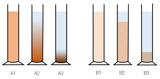
図1 シリンダーによる粒子沈降の経時変化の事例:(A)水田などの泥水、(B)活性汚泥の混合液
1:沈降開始時の状況、2:初期沈降の状況、3:終期沈降の状況
Fig.1 Examples of particles settling phenomenon in a cylinder over time: (A) paddy field muddy water, (B) mixture of activated sludge.
Settling situation: 1 at the start, 2 initial stage, 3 final stage.
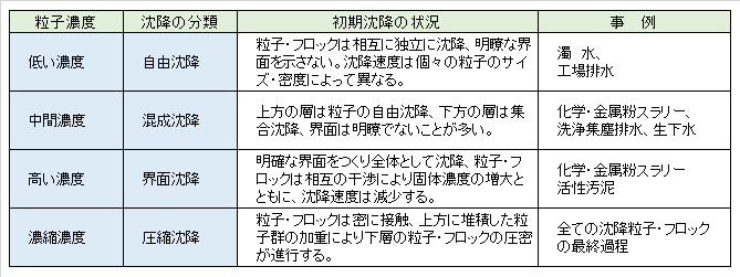
土木工事現場の泥水・工場の沈降分離工程・生活排水の沈降分離工程での代表的な固形粒子の沈降特性を表1にまとめて示す。
Table 1 shows the settling characteristics of typical solid particles in the muddy water at the civil engineering site, the settling separation process of the factory, and the settling separation process of domestic wastewater.
Table 1 Classification of typical settling characteristics of solid particles.
(2)界面沈降速度
汚泥の初期濃度を変えて、汚泥界面(例えば、図1:B1~B3)の高さを一定時間ごとに測定すると、図2に示すような界面沈降曲線が得られる。沈降の初期においては、界面の沈降速度はほぼ一定で直線に近いので、定速沈降領域という。ある時間を過ぎると、沈降速度が急激に減少するようになり、これを減速(または圧密)沈降領域という。定速から減速に変化する時点を境界圧密点(または臨界点)というが、汚泥の濃度や種類によっては、明瞭に認められないこともある。
(2) Interface settling velocity
When the height of the sludge interface (for example, B1 to B3 in Fig.1) is measured at fixed intervals by changing the initial concentration of the sludge, an interface settling curve as shown in Fig.2 is obtained. In the early time of precipitation, since the settking rate of the interface is close to a straight line at a substantially constant, the constant velocity settling region called. After a certain period of time, the sedimentation velocity suddenly decreases, which is called a deceleration (or compression) settling region. The point at which the speed changes from constant speed to deceleration is called the boundary point (or critical point), but it may not be clearly recognized depending on the concentration and type of sludge.
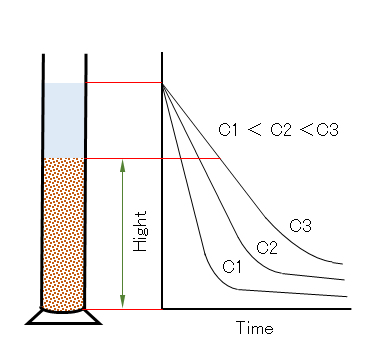
図2 汚泥の界面沈降曲線 C1~C3:初期汚泥濃度
Fig.2 Sludge interfacial sedimentation. Curve C1 to C3: initial sludge concentration.
(3)沈降特性と分離プロセス
重力沈降によって固液分離操作を行う場合には、効率的な面から2つに分けられる。すなわち、上記の定速沈降領域を利用するプロセスを清浄沈殿池(槽)(クラリファイヤー、または沈殿池)といい、減速(または圧密)沈降領域を利用するプロセスを沈殿濃縮池(槽)(シックナー、または濃縮池)と称している。沈殿池および濃縮池の特性と設計については、下記に示す。
目次へ
(3) Settling characteristics and separation process
When the solid-liquid separation operation is performed by gravity settling, it can be divided into two in terms of efficiency. That is, the process using the above-mentioned constant velocity settling is called a clean settling tank (or clarifier), and the process using the slower (or compression) settling is thickening tank (thickener). The characteristics and design of the clarifier and the thickener are shown below.
To table of contents
2.沈降速度
粒子が流体中で沈降するとき、粒子には重力と流体から受ける抵抗力が働き、やがて、一定の速度で沈降するようになる。この速度を終末沈降速度という。この速度は、流体のレイノルズ数(Re)によって、ストークス(Re≦2)、アレン(2<Re≦500)、ニュートン(500<Re≦105)の各式が提案されているが、汚水処理で扱う沈殿池(槽)の沈降分離の多くは、Re≦2である。
ストークスの式は、次式で示される。
Vs:粒子の沈降速度[cm/s]、g:重力の加速度[cm/s2]、μ:水の粘度[g/cm/s]、ρs:粒子の密度[g/cm3]、ρ:液体の密度[g/cm3]、d:粒子の直径[cm]
この式に示されているように、粒子は水より重いほど、また、粒径の2乗に比例して速く沈降することとなる。粒径が10倍になれば、沈降速度は100倍となる。凝集法は、微細な粒子を、それらの凝集体に形成させて、その粒径を大きくして沈降分離効率の向上を目的とする手法である。
2. Settling velocity
When the particles settle in the fluid, the particles receive gravity and a resistance force received from the fluid, and eventually they settle at a constant velocity. This velocity is called the terminal sedimentation velocity . For this velocity , the Stokes (Re ≤ 2), Allen (2 < Re ≤ 500), and Newton (500 < Re ≤ 105) formulas have been proposed depending on the Reynolds number (Re) of the fluid. Most of the sedimentation separations of the settling tanks (tanks) handled are Re≦2.
The Stokes equation is given by the following equation.
Vs: Settling velocity of particles [cm/s], g: Acceleration of gravity [cm/s2 ], μ: Viscosity of water [g/cm/s], ρs : particle density [g/cm3], ρ: liquid density [g/cm3], d: particle diameter [cm]
As shown in this equation, the heavier the particles than water , the faster the particles settle in proportion to the square of the particle size. When the particle size is 10 times, the sedimentation rate is 100 times. The flocculation process is a method for forming fine particles into flocs thereof and increasing the particle size to improve the sedimentational separation efficiency.
流体力学では、流体の慣性力と粘性力との比で定義される無次元量で示される。レイノルズ数は、層流や乱流のような流れの異なる流域を特徴づけるためにも利用される。層流においては、低いレイノルズ数において発生し、粘性力が支配的で、滑らかで安定した流れが特徴である。乱流については、高いレイノルズ数において発生し、そこでは慣性力が支配的となり、無秩序な渦や不安定な流れが特徴である。流体の流れは、一般的には無秩序であり、通過する水路の形状(円・矩)や表面積の粗さなどの非常に小さな変化が異なる流れの発生原因となる。
In fluid mechanics, it is expressed as a dimensionless quantity defined by the ratio of the inertial force and the viscous force of the fluid. Reynolds number is also used to characterize different watersheds such as laminar and turbulent flows. Laminar flow occurs at low Reynolds numbers, is dominated by viscous forces, and is characterized by smooth and stable flow. Turbulence occurs at high Reynolds numbers, where inertial forces predominate and are characterized by chaotic eddies and unstable flows. The flow of a fluid is generally disordered, and very small changes such as the shape (circle, rectangle, etc.) of the passages and the roughness of the surface area cause different flows.
汚水中の固形粒子群では、様々な形状・密度・粒径が異なるので、前段でスクリーンや沈砂池などにより、ある程度、同一な種類の粒子群に分別される。それでも、形状・密度・粒径が異なるので、沈降速度に分布が認められる。例えば、同じ形状・密度の粒子群でも、その粒径が異なれば沈降速度に分布が生じ、また、粒径が同じでも、形状・密度が異なれば沈降速度に分布が生じる。沈降分離操作において、分布の幅が狭いほど、その分離効率が向上する。
目次へ
Solid particles in wastewater have different shapes, densities, and particle sizes, so they are separated into particles of the same type to some extent by a screen or sand basin in the previous stage. Even so, since the shape, density, and particle size are different, the sedimentation velocity has a distribution . For example, even in a group of particles having the same shape and density, if the particle size is different, a distribution of the sedimentation velocity is generated, and even if the particle size is the same, if the shape and the density are different, the settling velocity is distributed. In the settling separation operation, the narrower the distribution, the higher the separation efficiency.
To table of contents
3.沈殿池と水面負荷
以下に記載する原理・方式は、沈殿池の仕組みを理解する上で極めて重要なものであるが、自由沈降する粒子に適用する理想的な条件下で成立するのものであって、具体的に沈殿池を設計する場合には、個々の目的に応じて、実験的に設計値を求めることとなる。沈殿池には、上昇流式あるいは横流式(水平流式)が採用される。
3. Settling tank and surface load
The principles and methods described below are extremely important for understanding the mechanism of the settling basin , but they are established under ideal conditions applied to particles that settle freely , and When designing a settling tank, the design value will be experimentally determined according to the individual purpose. Ascending flow type or horizontal flow type is adopted for the sedimentation tank.
(1)上昇流式
上昇式沈殿池(図2(A))において、粒子の沈降速度Vsが汚水の上昇速度Vよりも大きければ、粒子は沈降し、小さければ汚水とともに流出する。汚水の上昇速度V[m/d]は次式で示される。
Q:汚水の流入量[m3/d]、A:沈殿池の面積[m2]
沈殿池の設計では、Vs > V となるように、沈殿池の面積Aを設定する。Vは流速であるが、これを水面積負荷または表面積負荷という。流入量Qで、粒子の沈降速度Vsの沈殿池の必要面積Aは、(1)式より、A > Q/Vs となる。
例えば、流入水量10,000m3/d、粒子の沈降分離速度15mm/minのとき沈殿池の必要面積は、次のようになる。
= 463[m2]
(1) Upflow type
In the rising sedimentation basin (Fig. 2(A)), if the settling velocity Vs of the particles is larger than the rise velocity V of the wastewater, the particles settle, and if the sedimentation velocity Vs is smaller, the particles flow out together with the wastewater. The rising speed V [m/d] of wastewater is expressed by the following equation.
Q: Inflow of sewage [m 3 /d], A: Area of settling basin [m2]
In the design of the settling tank, the area A of the settling tank is set so that Vs > V. V is the flow velocity, which is called surface load or surface area load. The required area A of the settling tank with the inflow rate Q and the settling velocity Vs of the particles is A> Q/Vs from Eq.(1).
For example, when the inflow rate is 10,000 m3/d and the settling separation rate of particles is 15 mm/min, the required area of the settling tank is as follows.
= 463[m2]
(2)横流式
横流式(図2(B))(または、水平流式)では、汚水が流入してから流出するまでの時間(汚水の滞留時間)T[d]内に、沈殿池の底部までに沈降する必要がある。沈降速度Vs[m/d]とすると、粒子の沈降する水深Hs[m]は、次式で示される。
一方、深さH[m]、面積A[m2]の沈殿槽に、流入量Q[m3/d]の汚水が流入すると、その滞留時間Tとの関係は、次式で示される。
Hs>Hであれば、汚水が流出する前に、粒子が底部まで沈降するので、次式が成立する。
以上のことから、上昇流式でも横流式でも、同一の種類の粒子に対しては、設計条件は同一の表面積の沈殿池となる。
横流式は、上昇流式よりも効率がよい。この理由は、図2(B)に示す整流壁P1のH’の位置から流入した粒子の沈降速度がV’s<Vであったとしても、整流壁P2に達する前に沈殿池の底面に達する沈降速度であれば、その粒子が分離できることによる。
目次へ
(2) Crossflow type
In the cross-flow method (Fig.2(B)) (or horizontal flow method), the sewage settles to the bottom of the settling tank within the time (retention time of sewage) T[d] from the inflow to the outflow. There is a need. If the sedimentation velocity is Vs[m/d], the water depth Hs[m] at which the particles settle is expressed by the following equation.
On the other hand, when the inflow amount Q[m3/d] of sewage flows into a settling tank having a depth H[m] and an area A[m2], the relationship with the retention time T is shown by the following equation.
If Hs > H, the particles settle to the bottom before the wastewater flows out, so the following equation holds.
The cross-flow type is more efficient than the up-flow type. The reason for this is that even if the settling velocity of particles flowing in from the position H’of the rectifier wall P1 shown in Fig.2(B) is V’s < V, and the particles can be separated when these reach the bottom of the settling tank before reaching the rectifier wall P2.
Table of contents
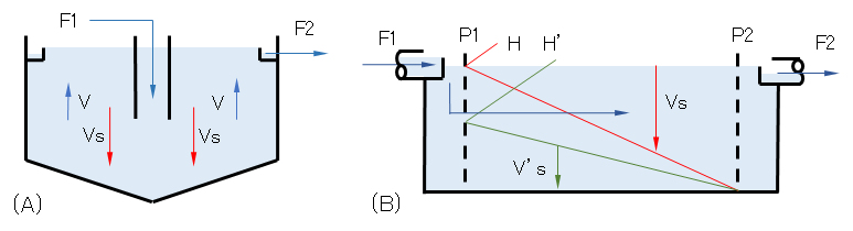
図3 代表的な沈殿池:(A)上昇流式、(B)横流式
F1:流入原水、F2:処理水、P1 & P2:整流壁
Fig.3 Typical settling basin: (A) Upflow type, (B) Crossflow type.
F1: Inflow raw water, F2: Treated water, P1 & P2: Rectifier wall.
4.連続沈殿濃縮池
化学工業での析出沈殿物(工業原料の生産)の濃縮や大型浄化槽・下水道処理施設での汚泥の濃縮などに、連続沈殿濃縮池が利用される。この操作により、汚泥容積は1/2~1/4程度までに減容される。濃縮池では、上澄み層、沈降層、圧縮層が形成され、一定の流量で原汚泥が供給される条件では、池内の各層は定常状態に保たれる。
連続沈殿濃縮のモデルを図4に示す。物質収支は次式で示され、上澄み液が清浄(Cs ≫ Co)であれば、式(3)で近似される。
Ci・Qi = Cs・Qs (3)
4. Continuous thickener
The continuous thicknener is used for concentrating the precipitates (production of industrial raw materials) in the chemical industry and for concentrating sludge in large septic tanks and sewerage treatment facilities. By this operation, the sludge volume is reduced to about 1/2 to 1/4. In the theckener, a supernatant layer (zone or region), a hindered settling layer, and a compression layer are formed, and under the condition that the raw sludge is supplied at a constant flow rate, each layer in the basin is kept in a steady state.
A model of continuous settling concentration is shown in Fig.4. The mass balance is shown by the following formula, and if the supernatant liquid is clean (Cs >> Co), it is approximated by Eq.(3).
Ci×Qi = Cs×Qs (3)
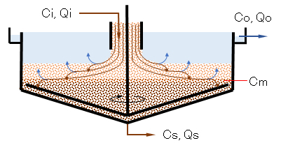
図4 連続沈殿濃縮のモデル
Q、C:流量、汚泥濃度; i:供給原汚泥、o:流出上澄み液、s:排出濃縮汚泥
Fig.4 Model of continuous thickener.
Q, C : flow rate, sludge concentration; i: raw sludge, o: effluent supernatant, s: discharged thickened sludge.
質量沈降速度
汚泥濃度C[kg/m3]、その沈降速度Vs[m/d]としたとき、
Gs[kg/m2/d]は、質量沈降速度といわれる。1.固形粒子の沈降特性で述べたように、Cが低くて、自由沈降に近い領域では、濃度が多少変化してもVsはあまり影響を受けないので、Gsの値はCとともに増大する。Cがさらに高くなると粒子同士の干渉が激しくなって、Vsは次第に小さくなり、ついにはゼロに漸近するので、Gsもゼロに近づいていく。この状況を、汚泥濃度Cに対して質量沈降速度Gsをプロットすると、図5の②(緑線)のような挙動を示す。
ところで、シックナー内部では、濃縮汚泥の排出量Qsによって下向きの流れが生じる。表面積A[m2]とすると、汚泥の下向き速度はQs/Aとなるので、この効果による質量沈降速度Gt[kg/m2/d]は、次式のようになる。
連続式シックナーでは、QiとQsは一定に保たれているので、汚泥濃度Cと質量沈降速度Gtの関係は図5の青線①のように直線関係にある。
Mass settling velocity
When sludge concentration C [kg/m3] and its settling velocity Vs [m/d] are
Gs [kg/m2/d] is called mass settling velocity. As described in “1. settling characteristics of solid particles“, in the region where C is low and particle settling is not hindered, Vs is not affected so much even if the concentration is changed a little, so that the value of Gs increases with C. When C becomes higher, the interference between particles becomes more intense, Vs becomes gradually smaller, and finally approaches a zero, so Gs also approaches zero. This situation is explained as the behavior like a green curve ② in Fig.5, by plotting the mass sedimentation rate Gs against sludge concentration C.
By the way, inside the thickener, a downward flow occurs due to the discharge amount Qs of the concentrated sludge. If the surface area A[m2] is used, the sludge downward velocity is Qs/A, so the mass settling velocity Gt [kg/m2/d] due to this effect is as follows.
In continuous thickener, Qi and Qs are kept constant, so the relationship between sludge concentration C and mass settling velocity Gt is linear as shown as a blue line ① in Fig.5.
連続シックナーの表面積
シックナー内での、総質量沈降速度Gは、汚泥自身の沈降によるものGsと汚泥排出の流れによるもの合計Gtとなり、式(4)および(5)から次式が得られる。
汚泥濃度CとGの関係を図示すると、図5の赤曲線③のようになる。このことから、供給汚泥濃度Ciから排出汚泥濃度Csに至るまでのある濃度Cmにおいて(Ci < Cm < Cs)、総質量沈降速度Gは極小値Gmを示すこととなる。この沈降速度Gmに対応する濃度Cmの汚泥層が汚泥処理能力を決定することとなる。
図5の点線で示すように、Cm値は曲線③の極小値、または曲線②の変曲点から求める。Gm値は、曲線③の極小値を通る水平線か、あるいは、曲線②の変曲点とCs点を結ぶ直線と、G軸との交点のいずれかによっても求めることができる。
定常状態では、式(7)が成立するので、式(8)が得られ、供給汚泥のCi、Qi、Gmの各値を用いて式(8)より、必要な表面積Aが決定できる。
A = Ci・Qi / Gm (8)
具体的には、図2に示す方法により、汚泥濃度Cを変えて界面沈降速度Vsを測定し、式(2)~(4)より、図5の曲線①~③で示すC-G曲線を作成し、Gm値を作図法により求める。
Surface area of continuous thickener
The total mass settling velocity G in the thickener is Gs due to the sedimentation (or settling) of the sludge itself and the total Gt due to the sludge discharge flow, and the following equations are obtained from equations (4) and (5).
To illustrate the relationship between the sludge concentration C and G, a red curve ③ is obtained in Fig.5. From this, the total mass settling velocity G shows a minimum value Gm at a certain concentration Cm from the supplied sludge concentration Ci to the discharged sludge concentration Cs (Ci < Cm <Cs). The sludge layer with a concentration of Cm corresponding to the settling velocity Gm determines the sludge treatment capacity. As shown by the dotted line in Fig.5, the Cm value is obtained from the minimum value of curve ③ or the inflection point of curve ②. The Gm value can also be obtained by either the horizontal line passing through the minimum value of curve ③ or the intersection of the straight line connecting the inflection point and Cs point of curve ② with the G axis. In the steady state, Eq.(7) is established, so Eq.(8) is obtained, and the required surface area A can be determined from the Eq.(8) using the respective values of Ci, Qi, and Gm of the supplied sludge.
A = Ci×Qi/Gm (8)
Specifically, the interfacial sedimentation velocity Vs is measured by changing the sludge concentration C by the method shown in Fig. 2, and Eqs. (2) to (4 ), create C-G curves shown by curves ① to ③ in Fig.5, and find the Gm value by the drawing method.
シックナーの設計と運転
排泥量Qsを増減すれば、図5の直線①の傾斜が増減し、それに応じてG曲線③が上下し、GmおよびCsの値が変化して物質収支の平衡が保たれる。排泥濃度を高くするには、排泥量を絞り直線①の傾きを小さくすればよいが、それに伴ってGmも小さくなるので、給泥量Qiを減らすか、シックナーの面積Aを大きくしなければならない。限界値Gm以上の汚泥が供給されると、シックナー内に汚泥が次第に蓄積し、ついには汚泥が越流することとなる。
目次へ
Thickener design and operation
If the sludge amount Qs is increased or decreased, the slope of the straight line ① in Fig.5 will be increased or decreased, the G curve ③ will be moved up or down accordingly, and the values of Gm and Cs will be changed to maintain the balance of mass balance. In order to increase the sludge concentration, it is sufficient to reduce the sludge amount and decrease the slope of the straight line ①, but Gm also decreases accordingly. Therefore, the sludge supply amount Qi must be reduced or the thickener area A must be increased. When the sludge with a limit value of Gm or more is supplied, the sludge gradually accumulates in the thickener and eventually the sludge overflows.
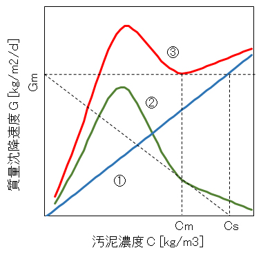
図5 汚泥の濃度Cと質量沈積速度Gの関係
① Gs = C・Vs、② Gt = C・Qs/A、③ G = Gs + Gt
Vs:汚泥界面の沈降速度[m/d]、Qs:濃縮汚泥の排出量[m3/d]、A:シックナーの表面積[m2]
Fig.5 Relationship between sludge concentration C and mass deposition rate G.
① Gs = C×Vs, ② Gt = C×Qs/A, ③ G = Gs + Gt
Vs: Settling velocity [m/d], Qs: thickened sludge discharge [m3/d], A: Surface area of thickener [m2].
5.傾斜板による沈降効率化
(1)傾斜板の原理
傾斜板の発想
容器を傾斜したときの沈降現象は、Boycottが試験管に入れた血液(赤血球)の沈降速度が、傾斜した試験管において速くなること発見した。これが沈殿池への傾斜板導入の発想となった。活性汚泥などの懸濁液を入れ、ゴム栓で密封したメスシリンダーを傾斜して沈降速度を観察すると傾斜角(θ)が小さいほど沈降分離速度が速いことが観察される。
5. Increasing settling efficiency with inclined plates
(1) Principle of inclined plate
Idea of inclined plate
The sedimentation phenomenon when the container was tilted was found by Boycott to accelerate the sedimentation rate of blood (red blood cells) placed in the test tube in the tilted test tube. This was the idea of introducing inclined plates into the settling device. When a graduated cylinder containing a suspension such as activated sludge and sealed with a rubber stopper is tilted and the sedimentation speed is observed, it is observed that the sedimentation separation speed increases as the inclination angle (θ) decreases.
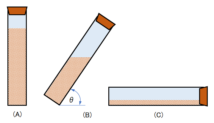
図6 傾斜メスシリンダー内の沈降速度の様子
Fig.6 Behavior of sedimentation velocity in the inclined measuring cylinder.
上記図1のB1~B2に示す懸濁粒子であって、図2に示す理想的な定速沈降特性領域に適用した傾斜板の原理について説明する。
図8に示すように沈殿池の分離面積A、傾斜板の面積So、その傾斜角θとし、界面沈降速度Vsとすると、t時間後に得られる沈殿池表面(qo)と傾斜板の下面(qt)に生成するそれぞれの清澄水量は次式で示される。
qt = Socosθ×Vst (10)
式(9)および式(10)の関係より清澄液の総量(qo + qt)から、沈降開始後t時間後における普通の沈殿池の清澄液量に対する傾斜板付設の沈殿池の清澄液量の増加率は、次式で示される。
ここで、上記の傾斜板を平行・等間隔にn枚付設したときの増加率は、次式で示される。
The principle of the inclined plate will be described, applying the characteristic settling region at the ideal constant velocity in Fig.2 which is also the suspended particles shown in B1 and B2 of Fig.1.
As shown in Fig.8 , when it is that the separation area A (horizental crossflow area) of the settling tank, the area So of the inclined plate , its inclination angle θ, and the interface settling velocity Vs, the clear liquid volume (qo) is obtained under the plate after t hours. The volume qt of the clear liquid generated under the back surface expressed by the following equation.
qt = Socosθ×Vs×t (10)
The relations of Eqs. (9) and (10) give the total volume of clarified liquid (qo + qt) to the volume of clarified liquid in the ordinary settling tank at t hours after the start of settling. The rate of increase in quantity is expressed by the following equation.
Here, the increase rate when n sheets of the inclined plates are installed in parallel and at equal intervals is shown by the following equation.
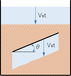
図8 傾斜板の基礎
θ:傾斜板の角度
Figure 8 Basics of inclined plate for settling.
θ: Angle of inclined plate.
式(12)から分かるように、付設する傾斜板の枚数が多いほど、その傾斜角θが緩やかなほど、沈殿池の清澄効率が向上することが理解できる。図9に示す普通池、傾斜板付設池(傾斜は板上部に沈積した粒子が自重により滑り落ちる角度θsdとする)および水平板付設(傾斜板と同じ枚数)池では、清澄液を得る効率(清澄速度)は(A)<(B)<(C)の順に高く(速く)なることが容易に理解できる。すなわち、傾斜板または平行板を沈殿池に設置する事により通常Hの沈降距離をhsまたはhpまで短縮できる。このことは、hs/Hまたはhp/H倍沈降時間が短縮され、沈降面積をH/hsまたはH/hp倍拡げる事を意味する。
ところが、沈殿池(C)では、板状に沈積した粒子(沈積汚泥)の排泥が困難である。このことから、板状上に沈積した汚泥が自重落下する沈殿池(B)のモデルが実用化されている。上水場での凝集沈殿池においては、一般的に、θsd = 60° とされている。
As seen from Eq.(12), it can be understood that the clarifying efficiency of the settling tank is improved as the number of installed inclined plates is increased and the inclination angle θ is decreased. In the tank with the inclined plate (the inclination is the angle θsd) and the horizontal plate (the same number as the inclined plate) shown in Fig.9, it can be easily understood that the clarification rate becomes higher (faster) in the order of (A) < (B) < (C). That is, the settling distance of normal H can be shortened to hs or hp by installing an inclined plate or a parallel plate in the settling tank. This means that the settling time is shortened by hs/H or hp/H and the settling area is expanded by H/hs or H/hp.
However, in the settling tank (C), it is difficult to discharge the layered particles (sludge). For this reason, a model of a settling tank (B) where sludge deposited on a plate falls by its own weight has been put to practical use. In coagulation settling pond for tap water, θsd = 60° is generally adopted.
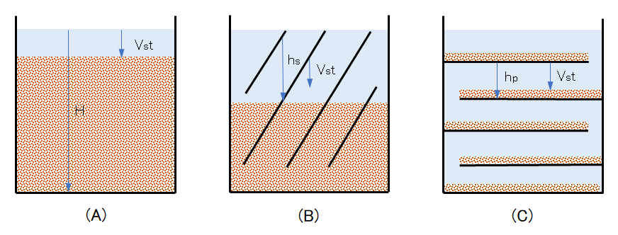
図9 傾斜板のモデル
(A)普通の沈殿池、(B)平行傾斜板付設の沈殿池、(C)平行水平板付設の沈殿池
Fig.9 Model of inclined plates.
(A) Ordinary settling tank, (B) Settling tank with parallel inclined plates, (C) Settling tank with parallel horizontal plates.
(2)傾斜板沈殿装置
傾斜板モジュール
図10に傾斜板の組立(モジュール)事例を示す。沈殿粒子は各傾斜板の表面に沿って自重により下降(→)し、清澄液は各裏面に沿って上昇(→)する。各傾斜板の上端と下端にはスリットが設けてあり、上昇する清澄水流と下降する沈殿粒子流を整流して、混合や水の混合を防いでいる。この上昇流と下降流とを巧みに利用した構成を発明したのは宇野昌平氏であった。傾斜板上部の沈積粒子の下降流と傾斜板下部の清澄液の上昇流とをジグザグ構成によって完全に分離したことが特徴である。
このような配列は、懸濁液濃度が高いとき(表1の界面沈降)に効果が発揮される。希薄懸濁液(表1の自由沈降)に対しては、上昇流と下降流とは明確に分離しないので、このようなモジュールは適用できない。また、このモジュールは、上昇流式沈殿池に採用すると、屈曲部で清澄液の上昇流と沈殿粒子の下降流が衝突して混合が起こり分離効果は半減する。
(2) Inclined plate sttling device
Inclined plate module
Figure 10 shows an example of the assembly (module) of the inclined plate. The precipitated particles descend (→) along the surface of each inclined plate by their own weight , and the clarified liquid rises (→) along each back surface. Slits are provided at the upper and lower ends of each inclined plate to rectify the ascending flow of clarified water and the descending flow of settled particles to prevent these flows from mixing. It was Dr. S. Uno who invented the structure that skillfully utilized the ascending and descending flows. It is characterized in that the descending flow of the settled particles above the inclined plate and the ascending flow of the clarified liquid below the inclined plate are completely separated by the zigzag configuration.
Such an arrangement is effective when the suspension concentration is high (zone or hindered settling in Table 1). For dilute suspensions (free settling in Table 1), such a module is not applicable as the upflow and downflow are not clearly separated. Further, when this module is adopted for an upflow type settling tank, the upflow of the clarifying liquid and the downflow of the settling particles collide with each other at the bent portion to cause mixing, and the separation effect is halved.
図10示すモジュールでは、清澄液と懸濁粒子液は逆方法に流れている。このため両液体の境界面では乱れが生じ分離効率が悪くなる。この欠点を改善したのが下記に述べるモジュールである。
この方式は、図10のジグザグ構造の最上段のみを延長し、傾斜板裏面の清澄液流路の下端に集水装置を取り付けたモジュールの導入である。原水を上部より導入し、清澄液と粒子液の流れを同じ方向として、両液の混合を防ぐとともに、清澄液の下降流が沈殿粒子の下降流速度を促進するので、傾斜板の角度を緩やかにできるので、沈降面積(式(5)のSocosθ)を大きくすることができる。
傾斜板モジュールの特徴は、傾斜板モジュールを多層に積み上げることができるとともに、上昇流方式だけでなく、図11に示すように傾斜板に沿って水平に原水を通水する方式(水平流方式)が採用できることにある。
In the module shown in Fig.10, the clarified liquid and the suspended particle liquid flow in the opposite way. Therefore, turbulence occurs at the boundary surface between the two liquids, and the separation efficiency deteriorates. The module described below has improved this drawback.
This method is an introduction of a module in which only the uppermost stage of the zigzag structure of Fig.10 is extended, and a collecting device is attached to the lower end of the clean liquid channel on the back surface of the inclined plate. Raw liquid is introduced from the top to keep the flow of the clarified liquid and the particles-settling liquid in the same direction to prevent mixing of both liquids, and the downward flow of the clear liquid promotes the downward flow velocity of the settled particles layer. Therefore, the settling area ( Socosθ in Eq.(5)) can be increased.
The characteristics of the inclined plates module are that the modules can be stacked in multiple layers, and it can be adopted not only for the upward flow method, but also for the method of horizontally flowing raw water along the inclined plates as shown in Fig.11 (horizontal flow method).
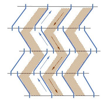
図10 傾斜板の組立(モジュール)と傾斜板内の分離現象 [井出、1976]
Fig.10 Assembly (module) of inclined plates and separation phenomenon in the inclined plates [Ide, 1976]
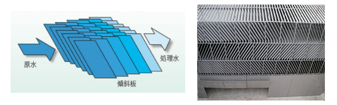
図11 水平流式傾斜板(左)と具体例(右)[積水アクワシステム]
Fig.11 Inclined plate module for settling of horizontal flow type (left) and the practical example (right) [Sekisui Aqua System].
傾斜板を組み合わせたモジュールの代わりに、図12の左図に示すような傾斜管を右図のようにモジュール(ユニット)化した沈降分離装置が開発された。傾斜管の形状として、正(長)方形、菱形、六角形、円形、V形などがある。一辺または相当直径は50cm前後である。同図では、各列ごとにクロスしているが、同一方向のモジュールもある。写真1に具体的な市販品の事例を示す。
傾斜管モジュールは、ユニットが強度的に堅牢で、各ユニットを横方向・奥行き方向に並べて沈殿池の面積に応じて導入できるとともに、支持枠・棚に設置するだけで利用できる特徴がある。
Instead of the module combining the inclined plates, a settling separation device was developed in which the inclined tube as shown in the left figure of Fig.12 was modularized as shown in the right figure. The shapes of the inclined pipes or tubes include a regular (long) square, a rhombus, a hexagon, a circle, and a V shape. One side or equivalent diameter is around 50 cm. In the figure, the columns cross each other, but there are modules in the same direction. Photos 1 show examples of commercial products.
The slant tube module is characterized in that the units are strong in terms of strength and can be installed by arranging the units side by side and in the depth direction according to the area of the settling tank and installing them on a support frame or shelf.
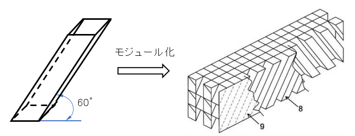
図12 傾斜管とそのモジュール [(右図)磯村豊水機工]
Fig.12 Inclined tube and its module [Isomura Yutaka Suikiko(right)]
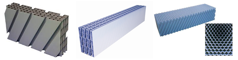
写真1 傾斜管モジュールの具体例 [(左)JFEアクワサービス機器、(中)前澤工業、(右)オルガ]
Photos 1 Specific examples of tilt tube modules [JFE Aqua Machine and Service(left), Maezawa Industries(center), Organo(right)].
(3)傾斜板沈殿池
傾斜板設置上の留意事項
沈降装置の形状により、水平流の中で用いるもの、上向流の中で用いるもの、どちらの方向の水流にも使えるものがある。
傾斜板沈殿池では、水流が沈降装置外を通ると、沈殿効率が著しく低下するので、短絡流が生じないようにする必要がある。池内への流入を均等にするために適正な整流壁を設け、また短絡流を防止するために阻流壁、阻流板、側流止めを設ける(図13のa、dなど)。また、沈殿効率を高めるために池内部での流速を定める、沈殿池で沈降装置内への流入が均等になるように、沈降装置を流入部に近接させて設置しないようにする、偏流によるフロックの巻き上げを防止するため沈降装置を流出部壁に近接させない、沈降装置下端と池底との間は 1.5m 以上あけて、堆泥の空間として確保するとともに、排泥設備の設置あるいは排泥作業、沈降装置の維持管理が円滑にできるようにする、等の注意が必要である。[水道施設設計指針, 2000]
(3) Inclined plate (Lamella) settler
Notes for installing inclined plate device
Depending on the shape of the settling device, there are those used in horizontal flow, those used in upward flow, and those that can be used for water flow in either direction.
In a sloping plate settling system, when a water flow passes outside the settling device, the settling efficiency is significantly reduced, so it is necessary to prevent a short-circuit flow from occurring. It is provided with an appropriate baffle wall in order to equalize the inflow into the basin or tank, and baffling wall in order to prevent a short circuit current, baffle, providing a side stream stops (a, d, etc. in Fig.13). In addition, the flow velocity inside the device is determined to increase the settling efficiency, and the settling device is not installed close to the inflow part so that the inflow into the device is uniform in the settling tank. Do not place the settling device close to the outflow wall to prevent winding up of the sewage, keep a space of 1.5 m or more between the bottom of the settling device and the bottom of the tank to secure a space for sediment layer, and install a sludge discharge facility or sludge discharge work. Care should be taken to ensure that the settling equipment can be maintained and managed smoothly. [JWWA, 2000]
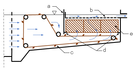
図13 横流式沈殿池に設置した傾斜板沈殿装置の事例
a:阻流壁、b:越流トラフ、c:汚泥掻寄機、d:側下部阻流板、e:傾斜板モジュール
Fig.13 Example of inclined plate settling device installed in a lateral flow type tank.
a: baffle, b: overflow trough, c: sludge scraper, d: lower side baffle, e: inclined plate module.
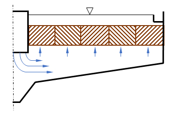
図14 円形上昇流沈殿池の傾斜板沈殿装置
スクレーパー、汚泥排出溝、歩廊など省略
Fig.14 Circular upflow settling tank with the inclined plate module.
Scraper, sludge discharge groove, etc. are omitted.
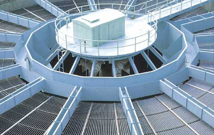
写真2 傾斜板設置円形沈殿の事例 [水道機工]
Photo 2 Example of circular clarifier with a inclined plate settling module [Suido Kiko].
参考文献・引用写真
磯村豊水機工株式会社:特開2010-264409
井出 哲夫:水処理工学-理論と応用-、技報堂出版(1976)
日本水道協会:水道施設設計指針 2000
オルガノ株式会社:https://www.organo.co.jp/products/technology-service/tapwater-sewerage-technology/00175_%e3%82%aa%e3%83%ab%e3%83%91%e3%83%83%e3%82%af/
水道機工株式会社:https://www.suiki.co.jp/hensen/75_84/80_1.html
積水アクワシステム株式会社:https://www.sekisuia.co.jp/infra/product/keisya/index.html
JFEアクワサービス機器株式会社:http://jfe-jms.co.jp/products/3-1.html
前澤工業株式会社:http://www.maezawa.co.jp/ja/product/jyosui/p-108.html
掲載日:2017年12月12日
更新日:2017年12月14日
更新日:2019年10月20日(「5.傾斜板による沈降効率化」を加筆)
References/Photos
Isomura Yutaka Suikiko Co., Ltd.: JP 2010-264409.
Tetsuo Ide : Water Treatment Engineering-Theory and Application-, Gihodo Publishing (1976).
JWWA (Japan Water Works Association): Water supply facility design guidelines 2000.
Organo Corporation: https://www.organo.co.jp/products/technology-service/ tapwater-sewerage-technology / 00175_% e3% 82% aa% e3% 83% ab% e3% 83% 91% e3% 83% 83% e3% 82% af /
Suido Kiko Kaisha, Ltd.: https: //www.suiki .co.jp/hensen/75_84/80_1.html
Sekisui Aqua System Co., Ltd.: https://www.sekisuia.co.jp/infra/product/keisya/index.html
JFE Aqua Machine and Service Co., Ltd.: http:// jfe-jms.co.jp/products/3-1.html
Maezawa Industries, Inc.: http://www.maezawa.co.jp/ja/product/jyosui/p-108.html
Publication: December 12, 2017
Update: December 14, 2017
Update: October 20, 2019 (Add “5. Increasing settling efficiency by inclined plate”)
